Minuteman X17 ECO CFS, Manual
The Minuteman X17 ECO CFS User Manual is your go-to resource for operating and maintaining this advanced product. Easily available for free download, this comprehensive manual provides step-by-step instructions, essential safety information, and troubleshooting tips. Get your copy exclusively from our website, ensuring a hassle-free user experience.
Share
Download


Reviews:
No comments
Related manuals for X17 ECO CFS
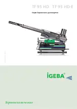
TF 95 HD
Brand: IGEBA Pages: 59
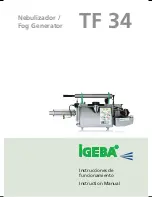
TF 34
Brand: IGEBA Pages: 48

Autopax PAX600H
Brand: Quasar Pages: 148

fs288
Brand: Feiyue Pages: 11

EXPRESSION 2028
Brand: Pfaff Pages: 4

MC9500
Brand: Janome Pages: 40

PHC17F
Brand: PHC Pages: 4

2-9824
Brand: GE Pages: 18

2-9868
Brand: GE Pages: 20

2-9866
Brand: GE Pages: 2

15638680 (REV. 1 E/S) 29878
Brand: GE Pages: 2

16018110
Brand: GE Pages: 2

2 2-9992 2-9992
Brand: GE Pages: 32

16174120
Brand: GE Pages: 48

29869 Series
Brand: GE Pages: 56

2-8111A
Brand: GE Pages: 84

2-9801
Brand: GE Pages: 1

Office Bridge IF-200
Brand: Muratec Pages: 41


