Minuteman M27000-00, Operation Service Parts Care
The Minuteman M27000-00 is a high-performance cleaning equipment with advanced features for efficient operations. Ensure longevity and optimal functioning of your device with our comprehensive user manual, available for free download at manualshive.com. This manual covers operation, service, parts, and care instructions for hassle-free maintenance and optimal performance.
Share
Download


Reviews:
No comments
Related manuals for M27000-00

Quilter's Choice BLQC2
Brand: Baby Lock Pages: 20
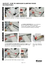
ELITE XT
Brand: Fastbind Pages: 3

AK85B
Brand: JUKI Pages: 5

CHARGER 2022 ABLT
Brand: NSS Pages: 16

160.459UK
Brand: Qtx Pages: 10

SPA-218
Brand: baalbaki Pages: 8

246-12
Brand: Singer Pages: 8

STRATUS 1000
Brand: TECshow Pages: 25

6019QC
Brand: Janome Pages: 40

133W102
Brand: Singer Pages: 14

KM 70/30 C Bp Adv
Brand: Kärcher Pages: 147

NOVAMATIC NM 2830
Brand: FUST Pages: 49

Modular TL2900
Brand: GBC Pages: 38

HZL-E61
Brand: JUKI Pages: 24

HZL-30Z
Brand: JUKI Pages: 44

DDL-9000C-F Series
Brand: JUKI Pages: 138

HZL - 353Z Series
Brand: JUKI Pages: 35

MultiPASS 800
Brand: Canon Pages: 51


