Minipa ET-2053, Instruction Manual
The Minipa ET-2053 is a versatile electronic tester that simplifies troubleshooting and measurements in electrical circuits. Ensure you maximize its potential by referring to the comprehensive Instruction Manual, available for free download from our website. Get all the details and guidelines you need to optimize your experience with the Minipa ET-2053.
Share
Download


Reviews:
No comments
Related manuals for ET-2053

405-014
Brand: Jula Pages: 29

69096
Brand: CEN-TECH Pages: 9

5200
Brand: C-LOGIC Pages: 4

4090
Brand: PeakTech Pages: 40

RC802-60B Series
Brand: Raisecom Pages: 13

22-602
Brand: Radio Shack Pages: 20

Hotwire 8776
Brand: Paradyne Pages: 112

HHM27
Brand: Omega Pages: 16
82005
Brand: Craftsman Pages: 22
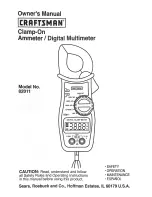
82011
Brand: Craftsman Pages: 12

AMP 4
Brand: AEG Pages: 20

38XR
Brand: Meterman Pages: 26

6420 DM
Brand: SEW Pages: 19

SBS-DMB-1000
Brand: Steinberg Pages: 21

U1252B
Brand: Keysight Technologies Pages: 3

U1451A
Brand: Keysight Technologies Pages: 19

8163A
Brand: Keysight Technologies Pages: 466

MRT-820C-SL
Brand: AFi Pages: 4


