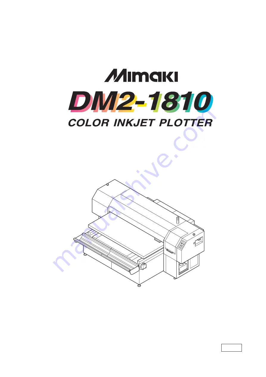
background image

MIMAKI ENGINEERING CO., LTD.

TKB Gotenyama Building, 5-9-41, Kitashinagawa, Shinagawa-ku, Tokyo 141-0001, Japan

Phone:  +81-3-5420-8671      Fax:  +81-3-5420-8687

URL: http: // www.mimaki. co. jp /

E-mail:  [email protected]

OPERATION  MANUAL

D201256

Summary of Contents for DM2-1810

Page 1: ...NEERING CO LTD TKB Gotenyama Building 5 9 41 Kitashinagawa Shinagawa ku Tokyo 141 0001 Japan Phone 81 3 5420 8671 Fax 81 3 5420 8687 URL http www mimaki co jp E mail trading mimaki co jp OPERATION MAN...

Page 2: ......

Page 3: ...T IN NO EVENT SHALL MIMAKI BE LIABLE FOR SPECIAL INCIDEN TAL OR CONSEQUENTIAL DAMAGES OR FOR LOSS OF PROFITS OF DEALER OR CUSTOMERS OF ANY PRODUCT Requests This Manual has been carefully prepared for...

Page 4: ...us laser radiation CDRH REGULATION The Center for Devices and Radiological Health for the U S Food and Drug Administration Implement regulations for laser products The Label shown below indicates comp...

Page 5: ...s the machine Please read and fully understand this Operation Manual before putting the machine into service It is also necessary to keep this Operation Manual on hand Make arrangements to deliver thi...

Page 6: ...ne 1 2 Moving the machine 1 3 Configuration and function 1 4 The Front 1 4 The Rear 1 5 Operation Panel 1 6 Capping station 1 8 Ink cartridge and Ink station 1 9 Precautions in handling the ink cartri...

Page 7: ...ning off the blower for the absorption table 2 22 CHAPTER 3 Daily Care Routine maintenance 3 2 When the machine is left unused for a long period of time 3 2 Precautions during cleaning 3 2 Maintenance...

Page 8: ...ntrol 5 16 CHAPTER 6 When Abnormal Conditions Are Encountered Abnormal conditions where no error massage appears 6 2 The machine cannot be energized 6 2 The machine cannot perform plotting 6 2 If imag...

Page 9: ...v APPENDIX Basic specifications A 2 Ink specification A 4 Consumable items A 5 Location of safety labels A 6 Function flowchart A 9...

Page 10: ...aximum The machine can plot on thick work such as board tile and siding Prints on extra wide work of 1870mm maximum Up to 1870mm wide work can be set for plotting over up to a1860mm wide area Indicati...

Page 11: ...that will facilitate the use of the machine Indicates the reference page for related contents Example of pictorials within the manual The symbol indicates the case where some phenomenon that requires...

Page 12: ...ns or the other optical observation sys tem Do not disassemble or modify the machine Never disassemble or remodel the main unit of the machine and the ink cartridge Disassembling remodeling any of the...

Page 13: ...cumulated on a medium will adversely affect the medium due to static electricity Frequently clean the capping station to eliminate dust and paper chips Dust in the head will also cause drops of ink to...

Page 14: ...dge as doing so may cause damage to the print circuit board CAUTION Ink cartridges If the ink cartridge is moved from a cold place to a warm place do not use for three hours Open the ink cartridge jus...

Page 15: ...tly exposed to blowing air from an air conditioner etc or you may get spattered with the ink A place that is not horizontal Do not place the machine where the machine can not be installed on a level s...

Page 16: ...on the LCD The content of display is shown in characters in a box as shown at right Operate the machine according to the explanation of the operation procedure and the content of dis play on the LCD I...

Page 17: ...e This chapter describes the daily cleaning Chapter 4 How to Set Functions This chapter describes the setting function Chapter 5 Maintenance Functions This chapter describes functions intended to corr...

Page 18: ...xiv...

Page 19: ...and function of each section of the machine as well as ink and work Table of contents Where to install the machine 1 2 Moving the machine 1 3 Configuration and function 1 4 Ink cartridge and Ink stati...

Page 20: ...embling the machine Install the machine considering enough space for the machine size and to perform plot operation Model Width Depth Height Gross weight DM2 1810 3070 mm 2560 mm 1350 mm 650 kg or les...

Page 21: ...chine take care not to apply excessive shock to it Be sure to adjust the level feet to level the machine at the new loca tion Method of moving the machine When moving the machine it must be held up by...

Page 22: ...let 7 Power switch It turns on off the power to the machine 8 Operation panel This panel has the operation keys required for operating the machine and the LCD for displaying set items etc page 1 6 9 W...

Page 23: ...2 Ink station Set the ink cartridges specified page 1 10 3 Air filter Filter out the dust or ink mist sucked the blower page 3 10 4 Blower door Open and close while turn On Off the blower main power s...

Page 24: ...e page 1 12 ENTER key Used to move to the lower level menu and establish the settings XY keys They are used to shift the carriage and the medium un der the LOCAL mode In ad dition they are used to se...

Page 25: ...oves to the next function When setting a plotting origin plotting area Shifts the carriage to the left Shifts the carriage to the right Shifts the work table away from you Moves the work table toward...

Page 26: ...aning the heads etc Cap It covers the nozzle so as to prevent the head nozzle from drying up Wiper It is used to clean the head nozzle The wipers are consumable parts If the wiper is deformed or the w...

Page 27: ...Refilling the ink cartridge can cause a trouble Remember that MIMAKI assumes no responsibility for any damage caused by the use of the ink cartridge replenished with ink Do not touch or stain the cont...

Page 28: ...tation supplies ink to the 2 front row of Carriage The Left ink station supplies ink to the 2 rear row of Carriage Remember these relationship when checking the heads for clogged nozzles replacing ink...

Page 29: ...cking The work can expand and contract due to room temperature and humidity The work have to be left in the atmosphere in which they are to be used for 30 minutes or more after unpacked Warps of work...

Page 30: ...lotting conditions 5 Pressing the VIEW key brings the work to the detaching position REMOTE mode The machine plots an image from data it receives During the plotting operation press the REMOTE key to...

Page 31: ...t 2 6 Setting the work on the machine 2 7 Establishing the origin and the print area 2 9 Covering in absorption holes located off the work 2 11 Checking and solving nozzle clogging 2 12 Correcting the...

Page 32: ...end of plotting For details on each item refer to the reference page Turn on the power on P 2 3 Check the head height P 2 6 Set the work P 2 7 Set the origin and printing area P 2 9 Plot the test patt...

Page 33: ...first displays BOOT and then displays the firmware version number 3 The message Please Wait appears flushing on the LCD The initial operation of the machine is performed To avoid injuries keep your ha...

Page 34: ...wer switch to I 3 Press the power switch once The switch light turns on The blower turns on and ready for atmospheric absorption During the CYCLE START mode the blower automatically turns off when the...

Page 35: ...ing In this case re start the machine and computer following the procedure described below STEPS 1 When opening the station cover during plot ting the message shown on the right will be displayed Stop...

Page 36: ...als Otherwise the head will touch the fluff and affect the print quality Confirm the head height setting value press the ENTER key in the LOCAL REMOTE and CYCLE mode page 2 20 STEPS 1 The machine ent...

Page 37: ...ble to the table page 1 11 Use some tape together if the air absorption function is unable to fix some work When plotting on T shirts or other cloths set them flat STEPS 1 Turn on the power to the mac...

Page 38: ...tted to each of the screws of the work holder Do not lose them when they are removed 2 The right and left work holders may be turned upside down as needed according to the work size 3 Place the work b...

Page 39: ...stablishing the origin and the print area Initial value The origin and the print area are set as follows by default until they are changed Effective printing area Work 15mm 15mm Origin 15mm Output dir...

Page 40: ...s as the carriage moves A cross shaped point mark appearing on the table or the work will be the display coordi nate 3 After deciding the origin press the ENTER key 4 Press the ENTER key Press the END...

Page 41: ...more when the holes located off the work also get cov ered on the table Cover in the holes by sheets such as papers and films as needed Use a roll support for a rolling work and a roll sheet for the a...

Page 42: ...ished test pattern shows any sign of abnormal conditions carry out the cleaning function To perform the test plot on a cut sheet medium use a medium whose size is A4 or larger with placed in landscape...

Page 43: ...e XY keys or to select the head block for cleaning Refer to page 1 10 Ink station 7 Press the XY or keys to set on off of the blocks that need cleaning Do not execute the head cleaning as for 8 Press...

Page 44: ...nge the work or establish the new origin 13 Repeat steps 2 and 3 and check the result of the test printing Repeat STEPS 2 to 10 until normal plotting result is obtained Replace the wiper and the ink c...

Page 45: ...ing disturbing neat plotting Correction for the work feed rate in online is available page 2 17 CORRECTING PATTERN Plot two bands Adjust the plot density so that the boundary of the two bands is plott...

Page 46: ...ction value from the output pat tern When ADJUST is changed to 30 the pattern moves by about 0 1 mm Determine the correction value referencing this amount of movement 11 Press the ENTER key Register t...

Page 47: ...REMOTE display The altered value ceases to be in effect and returns to the previous value A new value takes effect in real time The best effect can be obtained while checking the result The unit of t...

Page 48: ...Quality of image priority FAST Quality of speed priority HOST setting up drawing at the computer Plotting an image from source data Starting the plotting operation The following describes the method...

Page 49: ...plotting operation To interrupt the plotting operation stop the carriage and erase the receive data from the machine STEPS 1 Press the REMOTE key to stop the plotting operation 2 If data is being tran...

Page 50: ...ress the ENTER key to display the ink type 6 Press the ENTER key to display the firmware version and command 7 The ENTER key displays setting status The key displays the in use setup contents 8 The EN...

Page 51: ...he ink color which has completely run out The display at right indicates that slotC runs out STEPS 1 Either of the messages shown above is dis played on the LCD during plotting When INKnearEND appears...

Page 52: ...an extended period of time the nozzle will be clogged with dust If the power to the machine is turned off without the head capped return on the power to the machine When turning off the power be sure...

Page 53: ...Cleaning the wiper and ink caps 3 4 Cleaning the nozzle Nozzle Cleaning 3 7 Cleaning or replacing filter 3 10 Replacing the flushing tray ink absorber 3 11 When the waste ink tank becomes full 3 13 In...

Page 54: ...t allow moisture to get inside Turn off power and detach power cable before doing any maintenance Benzene thinner and chemical agents containing abrasives Such materials can deteriorate or deform the...

Page 55: ...e the cotton swab on the head nozzles The cotton swab may damage the nozzles and cause poor ink delivery Cleaning Tools Cleaning liquid bottle kit A29 SPC 0137 Option Cotton swabs Routine maintenance...

Page 56: ...ve the carriage out of the capping station by hand The Front side of each wiper is made of felt and the rear side is made of rubber Do not rub the felt side with a swab Instead press the swab against...

Page 57: ...n clean up the wiper Use and push a cotton swab contained clean ing liquid A29 to take off some dust on the felt surface Use a cotton swab contained cleaning liquid A29 to take off some inks on the ru...

Page 58: ...nal failure of the wiper resulting in error display 8 Wipe off ink or dirt adhered to the rubber of the cap and the ceiling of the wiper cover using cotton swab Clean the area at the end of the day s...

Page 59: ...head even Execute the Ink Filling function P 5 11 if the inks are mixed Operate it in the head only with the nozzle clogging Cleaning Tools Cleaning liquid bottle kit A29 SPC 0137 Option Syringe STEP...

Page 60: ...cotton swab contained cleaning liquid A29 to take off some inks on the rubber sur face 7 Clean the wiper and press the ENTER key 8 Fill the cap with the cleaning liquid A29 using a syringe 9 Close the...

Page 61: ...in 11 Press the ENTER key The initial operation is performed Remaining time is displayed After remaining time is over execute cleaning It displays the remaining cleaning time 12 Cleaning is completed...

Page 62: ...lean it with vacuum cleaner etc If the filter is clogged by ink adhesion replace the filter Outfit Filter for replacing 100pcs Order No M 3 It is the same as an ink absorber STEPS 1 Remove the filter...

Page 63: ...at the end the day s operation Outfit Ink absorber Order No M 3 It is the same as a mist filter STEPS 1 Press the FUNCTION key 2 Press the XY or keys to select MAINTENANCE Press the ENTER key 3 Press...

Page 64: ...er is placed flat and touching the tray Otherwise it may interfere with the head nozzles 10 Place the F cover from above Place the F cover all the way down A floating cover may cause trouble 11 Close...

Page 65: ...it stops dripping Dispose a long term unused waste ink regardless of its amount STEPS 1 Pull out the tank toward you When pulling out the waste ink tank hold the opening of the waste ink tank with pa...

Page 66: ...inge STEPS 1 Press the FUNCTION key once 2 Press the XY or keys to select MAINTE NANCE 3 Press the ENTER key Station is displayed 4 Press the ENTER key Carriage out is displayed 5 Press the XY or keys...

Page 67: ...g the suction pause period drop the cleaning liquid A29 until just before it overflows from the cap 9 Close the front cover and press the ENTER key Dry suction continues for 30 seconds and then the ma...

Page 68: ...function page 5 11 if the inks are mixed Cleaning Tools Cleaning liquid bottle kit A29 SPC 0137 Option Syringe STEPS 1 Press the FUNCTION key once 2 Press the XY or keys to select MAINTE NANCE 3 Press...

Page 69: ...off ink blots on wiper and bracket If dirt of curl is serious replace the wiper with a new one At the time of replacement be sure to terminate the machine operation and follow the wiper replacement pr...

Page 70: ...arriage moves away from the station 16 Open the station cover 17 Use and push a cotton swab contained clean ing liquid A29 to take off some dust on the felt surface Use a cotton swab contained cleanin...

Page 71: ...display 20 Fill the cap with the cleaning liquid A29 using a syringe Dry suction starts in cycles consisting of 10 seconds of suction followed by 10 seconds of pause Repeat the performance of the air...

Page 72: ...3 20...

Page 73: ...PTER 4 How to Set Functions This chapter describes how to set up the machine Table of contents Basic operations of menus 4 2 Registering a type 4 4 Setup functions 4 5 Change the display language DISP...

Page 74: ...key operation flow to invoke menus For detailed menu configuration refer to Appendix LOCAL X 800 Y 1200 FUNCTION SETUP ENT SETUP SELECT TYPE1 REMOTE X 800 Y 1200 REMOTE TYPE1 Print Mode ent ENTER ENT...

Page 75: ...vided into two the setup function and maintenance function Select either function 3 Select a type There are four types The FUNCTION mode can be set for each type depending on the media type used 4 Sel...

Page 76: ...lect any of types 1 through 4 5 Press the ENTER key Setting Plotting Conditions page 4 5 through 4 7 Changing the type If plotting conditions for types 1 through 4 have already been registered setting...

Page 77: ...her plotting speed with a lower plot quality than UNI D Return SPD The unidirectional plot within 1000mm width may cause nozzle drop out Nozzle drop out can be solved by head s return at low speed NOR...

Page 78: ...ne Refresh Solidification of ink can be prevented by refreshing the head during plotting If this function is executed in a dusty place or dry place ink in the head will be likely to solidify A larger...

Page 79: ...ing failures ON The head is cleaned automatically OFF The head is not cleaned automatically Setup Reset This function resets the current plotting conditions to the factory set plotting conditions Exec...

Page 80: ...o ENGLISH STEPS 1 Make sure that the mode is LOCAL mode 2 Press the FUNCTION key 3 Press the XY key twice 4 Press the ENTER key 5 Press the XY or keys to select the lan guage 6 Press the ENTER key The...

Page 81: ...ne 5 2 Plotting setup conditions LIST 5 4 Plotting HEX CODE DATA DUMP 5 5 When medium thickness is changed Print Adjust 5 6 Cleaning the station interior Station Carriage Out 5 8 When the message Repl...

Page 82: ...y of the maintenance functions it is necessary to perform the following opera tion on the operation panel You have to understand how to invoke the desired maintenance function to carry out maintenance...

Page 83: ...Carriage Out Ink Filling This is not normally used Perform it when nozzle clogging is still not solved In addition when Nozzle cleaning or Storage Wash is performed this may cause color mixture Perfor...

Page 84: ...PRINT adjust Indicates a correction value for dot position 3 REPLACE COUNTER Indicates the number of times the ink cartridges are replaced 4 VERSION Indicates the version of the firmware and memory c...

Page 85: ...HEX code The HEX code is an alphanumeric representation of plotting commands By using this code it is possible to check if there are any abnormal data commands When the DATA DUMP function is used to p...

Page 86: ...ress the ENTER key Plotting of the test patterns for the correction of dot position starts There are seven types of test patterns that are plotted 5 Press the XY or keys to correct the dot position of...

Page 87: ...on correction value on Patterns 1 to 7 and then terminate dot position correction 8 Press the END key to complete Print Adjust 9 Press the END key twice and the menu returns to the LOCAL mode Print Ad...

Page 88: ...cover then perform the fol lowing maintenance works for the station interior 1 Cleaning the ink caps page 3 4 2 Cleaning the wiper page 3 4 3 Cleaning the ink at the bottom of the slider page 3 3 4 Re...

Page 89: ...is to be really changed STEPS 1 Press the or keys to select Station 2 Press the ENTER key 3 Press the or keys to select Wiper Excng 4 Press the ENTER key The wiper moves toward you and the carriage mo...

Page 90: ...wiper guide shaft using a cotton swab or cloth If dirt is hard to remove use a cotton swab of cloth damp ened with water Cleaning the wiper guide shaft page 3 4 Extremely dirty wiper guide shaft may c...

Page 91: ...d 2 Press the or keys to select MAINTE NANCE 3 Press the ENTER key 4 Press the or keys to select Ink Filling 5 Press the ENTER key 6 Press the XY or keys to select a head with no ink 1256 3478 ABEF CD...

Page 92: ...rchase the optional Washing Liquid cartridge for water base ink in advance Before replacing ink empty out the waste ink tank STEPS 1 Make sure that the FUNCTION mode is dis played 2 Press the and key...

Page 93: ...is started 12 Repeat STEPS 8 and 9 13 Install new ink cartridges Insert ink cartridges in the ink stations The ink type for each ink station is displayed GPig Water pigment ink TPig Pigment ink for te...

Page 94: ...ure that the FUNCTION mode is dis played 2 Press the or keys to select the MAINTE NANCE 3 Press the ENTER key 4 Press the or keys to select the Informa tion 5 Press the ENTER key 6 Select Version then...

Page 95: ...eys to select the use head 4 Press the ENTER key 5 Press the XY or keys to select the ink type GPig Water pigment ink Standard attachment ink TPig Pigment ink for textile 6 Press the ENTER key 7 Press...

Page 96: ...1 Make sure that the FUNCTION mode is dis played 2 Press the or keys to select MAINTE NANCE 3 Press the ENTER key 4 Press the or keys to select Routine Ctrl 5 Press the ENTER key 6 Select Routine Flu...

Page 97: ...he ENTER key 4 Press the or keys to select Routine Ctrl 5 Press the ENTER key 6 Select Routine Cleaning then press the ENTER key 7 Press the or keys to select ON 8 Press the ENTER key 9 Press the or k...

Page 98: ...5 18...

Page 99: ...sures to be taken in the case where an to be taken in case an abnormal condition arises and an error message appears on the display Table of contents Abnormal conditions where no error massage appears...

Page 100: ...ected to the power outlet and the computer The machine cannot perform plotting This occurs when the data is not being transmitted to the machine properly It can also occur when any of the machine func...

Page 101: ...ate doubly or triply into paper feed Corrective measure Conduct the Feed Correct function page 2 15 Displacement is observed between outward and inward plotting The respective color ink injected by th...

Page 102: ...fficient The ink cartridge has run out of ink Not enough ink for cleaning Time to replace the wiper in the capping station with a new one has come and clean the bottom of the slider The wiper guide sh...

Page 103: ...the carriage Press the XY key or select Sta tion Carriage Out to cap the head page 5 8 Using the TPig ink Using the TPig ink Using the TPig ink Using the TPig ink The color of the loaded ink cartridge...

Page 104: ...erature Evn Temp is Low Temperature Evn Temp is High Temperature is below operable condition Temperature is below guaran teed Temperature is over below guaranteed Adjust environmental temperature Warn...

Page 105: ...ERROR 08 ENCODER ERROR 09 FPGA ERROR 19 HDC ERROR 10 COMMAND Control circuit board is defective Control circuit board is defective POWER 5V POWER 35V Control circuit board is defective Head connection...

Page 106: ...en overload The Ymotor has been overload Overcurrent error on the Xmotor has been detected Overcurrent error on the Ymotor has been detected Incorrect height of the capping station has been detected C...

Page 107: ...easure The wiper position is not correct Origin could not be detected Turn off the power to the machine for a while and then turn it on If the same error message appears again on the LCD contact your...

Page 108: ...6 10...

Page 109: ...ribes the specifications of the machine and components and the structure of the function menu Table of contents Basic specifications A 2 Ink specification A 4 Consumable items A 5 Location of safety l...

Page 110: ...each cartridge variable Medium type Unspecified media with a flat surface such as cardboards and tiles Sheet like works cloth canvas PET synthetic paper etc Work size Max printing area 1860 x 1010 mm...

Page 111: ...00VA Separate power is required for blower Recomended Available temp 15 C 30 C Environment Humidity 40 65 Rh No condensation Guaranteed temp 18 C 25 C Temperature change 10 C h or less Dust Equivalent...

Page 112: ...hin a month During 30 60 C Storage at temperature of 60 C is only permitted within 120 hours and at temperature of 40 C is permitted within a month The ink will freeze when it is left for a long time...

Page 113: ...t regular intervals to maintain adequate printing quality Contact your local MIMAKI distributor or call a local MIMAKI office for services Wiper 4pcs Order No SPA 0105 Ink absorber for the flushing tr...

Page 114: ...ed to this machine If any of them fall off or become illegible contact MIMAKI local distributor for a replacement All persons who install operate and maintain this machine should understand and follow...

Page 115: ...A 7 Location of safety labels 1 M903968 2 LHDM 04 Japanese PED 04 English 3 M901469 4 M901607 5 M901549 6 M903226 Japanese M904325 English 7 LHCM 02 Japanese PEC 02 English No Order No Label...

Page 116: ...A 8...

Page 117: ...A 9 Function flowchart...

Page 118: ...123456789012345 1234567890123456789012345 1234567890123456789012345 1234567890123456789012345 1234567890123456789012345 L 1 1234567890 1234567890 1234567890 1234567890 Err Display BOOT DM2 1810 V Plea...

Page 119: ...A 11 Filling 00 00 00 Display remaining time Function flowchart...

Page 120: ...234567890123456789012345 L 1 Origin Setup Origin Origin Setup X Y Head Height mm Head Height mm VIEW ENT VIEW DATA CLEAR ENT CLEAR X DATA VIEW CLEAR 1234567890123456789012345 1234567890123456789012345...

Page 121: ...345678901234567890123456 12345678901234567890123456 12345678901234567890123456 12345678901234567890123456 12345678901234567890123456 12345678901234567890123456 12345678901234567890123456 1234567890123...

Page 122: ...67890123456789012345 1234567890123456789012345 1234567890123456789012345 L 2 Clean 12563478 Select ABEFCDGH CLEANING ENTER Cleaning Type Normal CYCLE START REMOTE TYPE X Y REMOTE V360x360 STD 4P U Fee...

Page 123: ...0123456789012345678 1234567890123456789012345678 1234567890123456789012345678 1234567890123456789012345678 Display when Ink Near End occurs Alternataly display Display remaining time ENTER REMOTE V360...

Page 124: ...567890123456789012345 1234567890123456789012345 1234567890123456789012345 1234567890123456789012345 1234567890123456789012345 1234567890123456789012345 1234567890123456789012345 1234567890123456789012...

Page 125: ...fo Display V Key Default Check NG SET LG IK MT SV Default Check OK ENTER 12345678901234 12345678901234 12345678901234 12345678901234 If FUNC key OR X Shows all currentry occurred err Display current s...

Page 126: ...345 1234567890123456789012345 1234567890123456789012345 1234567890123456789012345 1234567890123456789012345 S 1 1234567890123456789012345 1234567890123456789012345 1234567890123456789012345 1234567890...

Page 127: ...n UNI D TYPE Layer 1 TYPE Time 0 0s TYPE PrintMode HOST TYPE Ink Layers HOST TYPE HOST TYPE Media Comp HOST TYPE Refresh HOST X Fine Fast X BI D X 1 9 X 0 0 9 9s X PLOT X PLOT X PLOT X PLOT X PLOT ENT...

Page 128: ...90123456789012345 1234567890123456789012345 1234567890123456789012345 S 2 1234567890123456789012345 1234567890123456789012345 1234567890123456789012345 1234567890123456789012345 1234567890123456789012...

Page 129: ...A 21 TYPE Refresh Level3 TYPE mm inch mm X Level0 Level3 X inch Function flowchart...

Page 130: ...89012345 1234567890123456789012345 1234567890123456789012345 1234567890123456789012345 1234567890123456789012345 1234567890123456789012345 1234567890123456789012345 S 5 1234567890123456789012345 12345...

Page 131: ...1234567890123 1234567890123 Output END X Y Width X OFF Y 12345678901234567890123456 12345678901234567890123456 12345678901234567890123456 12345678901234567890123456 12345678901234567890123456 12345678...

Page 132: ...56789012345 1234567890123456789012345 1234567890123456789012345 1234567890123456789012345 M 1 FUNCTION MAINTENANCE ENT MAINTENANCE List ent 1234567890123456789012345 1234567890123456789012345 12345678...

Page 133: ...56789012345 1234567890123456789012345 1234567890123456789012345 1234567890123456789012345 1234567890123456789012345 1234567890123456789012345 1234567890123456789012345 Return to Origin 1234567890123 1...

Page 134: ...0123456789012345 1234567890123456789012345 1234567890123456789012345 1234567890123456789012345 1234567890123456789012345 M 5 1234567890123456789012345 1234567890123456789012345 12345678901234567890123...

Page 135: ...012345 1234567890123456789012345 1234567890123456789012345 1234567890123456789012345 1234567890123456789012345 Drain tube Lock Wiper cleaning CNT clear Wiper Cleaning Completed ent ENTER X 1 99min Col...

Page 136: ...34567890123456789012345 1234567890123456789012345 1234567890123456789012345 1234567890123456789012345 1234567890123456789012345 1234567890123456789012345 M 5 1234567890123456789012345 1234567890123456...

Page 137: ...234567890 123456789012345678901234567890 123456789012345678901234567890 123456789012345678901234567890 123456789012345678901234567890 123456789012345678901234567890 123456789012345678901234567890 1234...

Page 138: ...6789012345 1234567890123456789012345 1234567890123456789012345 1234567890123456789012345 1234567890123456789012345 1234567890123456789012345 1234567890123456789012345 M 10 1234567890123456789012345 12...

Page 139: ...ashing 12345678ABCDEFGH Remove washing tools Washing 3 5 00 00 00 Suction Air Set Washing Liq 12345678ABCDEFGH Status verify 1234567890123456789012345 1234567890123456789012345 12345678901234567890123...

Page 140: ...CTION X 1234567890123456789012345 1234567890123456789012345 1234567890123456789012345 1234567890123456789012345 1234567890123456789012345 1234567890123456789012345 1234567890123456789012345 M 10 ENTER...

Page 141: ...eaning Cleaning ON ENTER Routine Cleaning Interval 1h X OFF X 1 48h Routine Flushing Flushing ON ENTER Routine Flushing Interval 1h X OFF X 1 24h Use Head InkType TPig XY Gpig Function flowchart MAIN...

Page 142: ...56789012345 1234567890123456789012345 1234567890123456789012345 1234567890123456789012345 1234567890123456789012345 1234567890123456789012345 1234567890123456789012345 1234567890123456789012345 S 1 12...

Page 143: ...A 35...

Page 144: ...D201256 1 10 02082005...

Page 145: ......

Page 146: ...PrintedinJapan MIMAKI ENGINEERING Co Ltd TI TM...

Reviews:

Related manuals for DM2-1810