


2
3
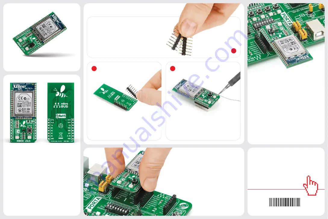
2. Soldering the headers
3. Plugging the board in
Once you have soldered the headers your
board is ready to be placed into the desired
mikroBUS
™
socket. Make sure to align the
cut in the lower-right part of the board with
the markings on the silkscreen at the
mikroBUS
™
socket. If all the
pins are aligned correctly,
push the board all the way
into the socket.
Turn the board upward again. Make sure
to align the headers so that they are
perpendicular to the board, then solder the
pins carefully.
Turn the board upside down so that
the bottom side is facing you upwards.
Place shorter pins of the header into the
appropriate soldering pads.
Before using your click board
™
, make sure
to solder 1x8 male headers to both left and
right side of the board. Two 1x8 male headers
are included with the board in the package.
4. Essential features
XBee click is network-compatible with other
devices that conform to ZigBee standards. The
module operates at the
2.4-2.5GHz
band, has
a wireless range of up to
60m
indoors, or up to
1.2km
outdoors (line-of-sight). The RF data
rate is up to
250 Kbps
. To simplify deployment,
the click features a commissioning button
and an associated LED. They allow you to
issue simple configuration commands with
subsequent button presses (joining or leaving
networks, self-identification, restoring default
values etc.)
1
XBee click carries the Xbee
®
and Zigbee-
compliant
XB24CZ7PIS-004
module with
a PCB antenna from Digi International. The
module provides wireless connectivity to
end-point devices in ZigBee mesh networks.
The board can communicate with the target
MCU either through the mikroBUS
™
UART
interface (TX, RX, RTS i CTS), or SPI (MISO,
MOSI, SCK, CS). Additional functionality is
provided by, Reset, and ATTN-DTR pins. Uses
3.3V power supply only.
1. Introduction
XBEE click Manual v101
0100000090060
XBEE
click
click
BOARDS
™
www.mikroe.com


