Miele T 9800, Descriptive Technical Documentation
The Miele T 9800 is a cutting-edge appliance designed to enhance your laundry routine. With its advanced features, it guarantees an efficient and hassle-free drying experience. Achieve optimal results with ease by referring to our comprehensive Operating and Installation Instructions manual, available for free download at manualshive.com.
Share
Download


Reviews:
No comments
Related manuals for T 9800
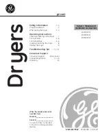
DSKS333E
Brand: GE Pages: 16

LUXOR
Brand: PALSON Pages: 17

NGD4800V
Brand: Amana Pages: 1

WILLMOP 35
Brand: TSM Pages: 102

ISF-620
Brand: German pool Pages: 17
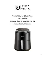
TXG-AF15T
Brand: ULTIMA COSA Pages: 20

ITALIA BRAVA BABFB1BA
Brand: BaByliss Pages: 12

HTD 8003 CB
Brand: BOMANN Pages: 24

TURBO Swift 0192-1-93
Brand: ASI Pages: 11

EconoRed Series
Brand: VASTEX Pages: 20

DV9 CGC Series
Brand: Samsung Pages: 28

DV17B9750 Series
Brand: Samsung Pages: 112

Unitized Spacemaker GTUP270EM
Brand: GE Pages: 3

UNITIZED SPACEMAKER WSM2700/80D
Brand: GE Pages: 3

Spacemaker WSKS2060T
Brand: GE Pages: 3

WNCD2050
Brand: GE Pages: 16

Spacemaker GUD37ESMMDG
Brand: GE Pages: 40

Spacemaker WSM2400L
Brand: GE Pages: 28


