Micsig TO1072, Abbreviated User Manual
The Micsig TO1072 User Manual is an essential guide to maximize the functionality of your TO1072 oscilloscope. Clear, concise instructions and detailed diagrams provide users with a seamless experience. Download this manual for free on manualshive.com to swiftly access the information you need to operate and troubleshoot your device effectively.
Share
Download


Reviews:
No comments
Related manuals for TO1072
PENPARTNER 2 -
Brand: Wacom Pages: 2
DTU-2231
Brand: Wacom Pages: 2

INTUOS 4
Brand: Wacom Pages: 2

GRAPHIRE 4
Brand: Wacom Pages: 2
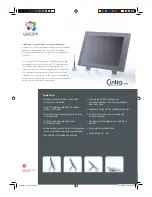
CINTIQ 15X
Brand: Wacom Pages: 49

DTU-1031
Brand: Wacom Pages: 63

BAMBOO TOUCH
Brand: Wacom Pages: 2

Cintiq 22HD
Brand: Wacom Pages: 65
Cintiq 21UX
Brand: Wacom Pages: 34
12WX
Brand: Wacom Pages: 2
Cintiq 21UX
Brand: Wacom Pages: 2

BAMBOO
Brand: Wacom Pages: 56
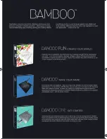
BAMBOO
Brand: Wacom Pages: 2
DTU-1031AX
Brand: Wacom Pages: 4

X70 EX
Brand: Viliv Pages: 26

rocky DK10
Brand: Amrel Pages: 82

JTAB 10
Brand: JadooTV Pages: 14

JTA-470
Brand: Jensen Pages: 17


