MGL Avionics Stratomaster Enigma, Manual
The MGL Avionics Stratomaster Enigma is a cutting-edge aviation device, boasting an array of advanced features. To fully understand and optimize its capabilities, download the comprehensive user manual for free directly from our website. Explore the Enigma's full potential with our detailed manual, providing in-depth instructions and valuable insights.
Share
Download


Reviews:
No comments
Related manuals for Stratomaster Enigma

Kibuk
Brand: Tecnodom Pages: 40

CVW-EXA124
Brand: Sanyo Pages: 30
DX6LN-MCU
Brand: Kysor/Warren Pages: 29

C2URHP2
Brand: Igloo Pages: 15

SAMOS 0.94
Brand: Igloo Pages: 40

OLA 1400.2 AG
Brand: Igloo Pages: 40

EWA 1400.2
Brand: Igloo Pages: 48

W.CFC23
Brand: Woodson Pages: 19
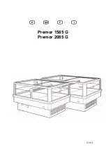
Premor 1585 G
Brand: Linde Pages: 63
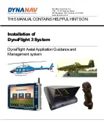
DynaFlight3
Brand: DYNANAV Pages: 18
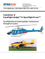
DynaFlight-AirAgII
Brand: DYNANAV Pages: 18


