MFZ Ovitor E6L, User Manual
The "MFZ Ovitor E6L" user manual is available for free download on our website. This comprehensive manual provides step-by-step instructions and valuable information on operating and maintaining the MFZ Ovitor E6L. Visit manualshive.com to access this manual and maximize your product's performance.
Share
Download


Reviews:
No comments
Related manuals for E6L

GEKO-L
Brand: O&O Pages: 24

LiftMaster PROFESSIONAL LYN300 Series
Brand: Chamberlain Pages: 99

LiftMaster 3575
Brand: Chamberlain Pages: 36

1029
Brand: Overhead door Pages: 32

A4
Brand: ProfiTech Pages: 8

Elpro 220
Brand: fadini Pages: 8

EXS40R
Brand: Doco Pages: 30

G30 Series
Brand: Roger Technology Pages: 16

DTM GO800
Brand: DTM System Pages: 12
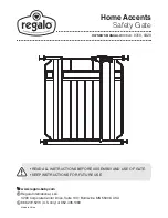
Home Accents 0310
Brand: Regalo Pages: 16

SFO
Brand: Sky-Frame Pages: 61

DKC500ACL
Brand: GATEXPERT Pages: 34

RapidCoil RC300 Series
Brand: Raynor Pages: 39

Bettis GVO-HP-FS Linear
Brand: Emerson Pages: 48

CA-P70
Brand: Kenwood Pages: 94

600
Brand: Easy Pages: 51

Security+ 711MD
Brand: Merik Pages: 80

790LMK
Brand: Merik Pages: 80


