background image

INSTRUCTION MANUAL

CAUTION: Read All Instructions Before Operating Equipment

MFJ ENTERPRISES, INC.

300 Industrial Park Road
Starkville, MS 39759 USA

Tel: 662-323-5869 Fax: 662-323-6551

COPYRIGHT

200

MFJ ENTERPRISES, INC.

5

C

Model MFJ-993B

VERSION 1

A

IntelliTuner

Automatic Antenna Tuner

TM

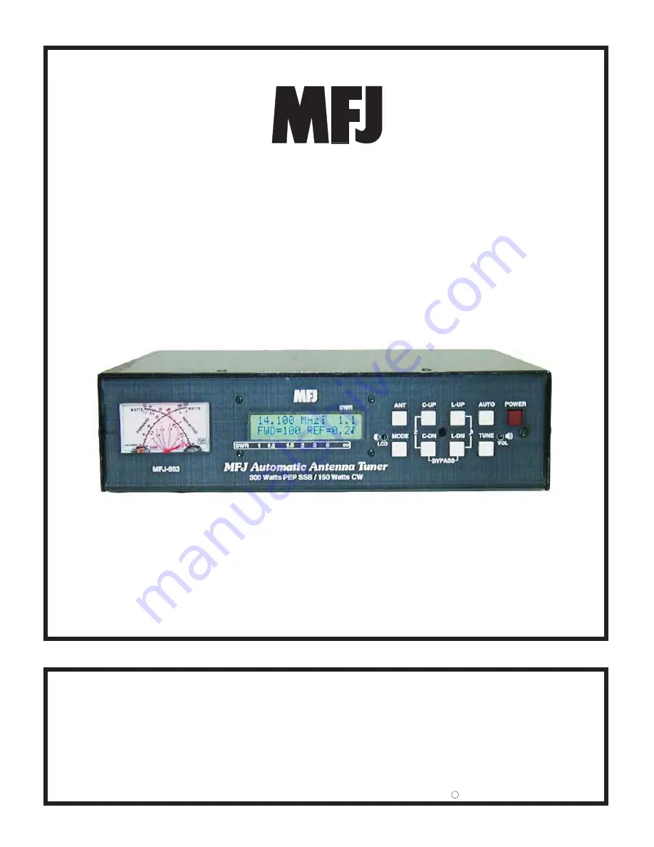
Summary of Contents for IntelliTuner MFJ-993B

Page 1: ...ructions Before Operating Equipment MFJ ENTERPRISES INC 300 Industrial Park Road Starkville MS 39759 USA Tel 662 323 5869 Fax 662 323 6551 COPYRIGHT 200 MFJ ENTERPRISES INC 5 C Model MFJ 993B VERSION 1A IntelliTuner Automatic Antenna Tuner TM ...

Page 2: ......

Page 3: ... and C DN Buttons 4 L UP and L DN Buttons 5 AUTO Button 5 TUNE Button 5 VOL Control 5 POWER Button 5 Back Panel 7 Power 7 Remote Port 7 Radio Interface 7 Transmitter 8 Ground 8 Balanced Line 9 Wire 9 Antenna 1 9 Antenna 2 9 Installation 9 SWR Wattmeter 10 THE MENUS Main Mode Menus 11 Digital Wattmeter Menu 11 Power Bar Meter Menu 11 SWR Bar Meter Menu 12 L Network Menu 12 Tuner Indicators 13 Anten...

Page 4: ...ATION Manual Tuning 18 Meter Codes and Audible Beeps 19 Foldback Circuit 20 Grounding Hints 21 Antenna System Hints 21 Location 21 Matching Problems 21 APPENDICES Resetting the Tuner 23 Factory Defaults 23 Delete Antenna Memory 24 Total Reset 24 Self Test 24 Power Down Circuit Test 25 Relay Test 26 Firmware Version Number via Meter 26 Setting the Speaker Volume 26 Wattmeter Calibration 27 SWR Brid...

Page 5: ...linco Interface Cable 8 Figure 6 Icom Interface Cable 8 Figure 7 SWR Wattmeter 10 Figure 8 Power Bar Meter High Range 12 Figure 9 Power Bar Meter Low Range 12 Figure 10 SWR Bar Meter 12 Figure 11 Main Mode Menus Display 13 Figure 12 Tuner Indicators 14 Figure 13 Power On Operations 23 Figure 14 MFJ 993B Circuit Block Diagram 30 TABLES Table 1 Memory Resolution 16 Table 2 Meter Needle Stationary Co...

Page 6: ...MFJ 993B IntelliTuner Automatic Antenna Tuner Instruction Manual 2003 2005 MFJ Enterprises Inc iv THIS PAGE IS LEFT BLANK INTENTIONALLY ...

Page 7: ...restored and you re ready to operate in milliseconds Each of two antenna selections has four banks of memory which can learn and remember more than 2500 frequencies and tuner settings per bank When you key your transmitter MFJ s InstantRecallTM checks its memory to see if you have operated that frequency before If so tuning is instantaneous and you re ready to operate If not MFJ s IntelliTuneTM al...

Page 8: ... 1 current balun for balanced line antennas Optional remote control Optional radio interface for compatible radios Specifications Impedance matching range 6 to 1600 ohms 300 watts or 6 to 3200 ohms 150 watts SWR matching range up to 8 1 for 50 ohms and up to 32 1 for 50 ohms 300 watts up to 8 1 for 50 ohms and up to 64 1 for 50 ohms 150 watts Minimum power for tuning 2 watts Maximum power while tu...

Page 9: ... BALANCED LINE binding posts and connect a jumper between the other two posts as indicated 4 Connect your ground connection to the GROUND post 5 Press the POWER button to turn on the MFJ 993B tuner Place the ANT button in the out position to select antenna 1 Press the AUTO button in to select semi automatic mode 6 Key your transmitter to output a carrier of 10 watts CW FM or AM 7 Press and hold th...

Page 10: ...ormation LCD Contrast Control A trimpot control that adjusts the contrast of the LCD display Use a small flat blade screwdriver and turn clockwise to increase contrast ANT Button Used to select the antenna to tune Button out selects Antenna 1 button in selects Antenna 2 The Antenna indicator on the main display indicates the selected antenna A balanced feedline or a single wire antenna is by defau...

Page 11: ...cond to bypass the tuner RF from the transmitter goes directly to the antenna with no matching Press and hold TUNE for 0 5 to 2 seconds to start the automatic tuning process The transmitter must be keyed first with at least 2 watts of power When the SWR is already below the target SWR pressing TUNE will fine tune the match for a lower SWR if possible StickyTune allows for one handed tuning operati...

Page 12: ...nds to start the tuning process press and hold for more than two seconds to toggle the StickyTune on and off Press in to select semi automatic mode out to select automatic mode Press to decrease inductance Press to increase inductance Press to decrease capacitance Press to increase capacitance Press to switch main modes and setup modes Press in to select antenna 2 out to select antenna 1 Press in ...

Page 13: ...EDs on the remote control The red Tuning LED lights to indicate tuning is in progress and the green SWR LED lights when the SWR is below the target SWR Note To use the remote control both the ANT and AUTO buttons on the automatic tuner must be pressed in otherwise Antenna 1 and Automatic mode are selected Radio Interface A 3 5 mm stereo phone jack for connecting to the tuner interface connector of...

Page 14: ...3 5 mm Stereo Phone Plug Pin 3 13 8V connects to the Center Pin of Power Plug Pin 4 Ground connects to the Sleeves of both 3 5 mm Stereo Phone Plug and Power Plug Figure 6 Icom Interface Cable The MFJ 5124K interface provides power and control between a Kenwood radio and the MFJ automatic tuner Supported Kenwood radios are TS 50S TS 450S TS 480HX TS 570S TS 690S TS 850S TS 870S TS 2000 and any Ken...

Page 15: ...le transmitting Disconnect all antennas from the tuner during lightning storms Always tune with low power about 10 watts Apply maximum power only after tuning up Never exceed tuner specifications Do not transmit with a high SWR for extended periods of time 1 Place the tuner in a convenient location at the operating position With a random wire or balanced line the feed through insulators may have h...

Page 16: ...s than four watts automatically set the meter to the low power range To cycle the meter range among low high and auto range press the TUNE and L DN buttons simultaneously The forward needle will read 300 for high range 30 for low range and 100 for auto range until the buttons are released When auto range is enabled a two dot vertical segment low range or a three dot vertical segment high range app...

Page 17: ... numeric reading of forward power appears at the end of the bar meters A power scale is printed just below the display on the front panel Each power bar meter is consisted of 60 bar segments When in the high power range each vertical bar segment consists of three dots Below 100 watts each bar segment represents two watts above 100 watts each bar segment represents 20 watts The forward bar meter ha...

Page 18: ... 1 to infinity The numeric reading of forward power appears at the end of the bar meter There is also an audio SWR indicator see SWR Beep Menu section on page 17 1 1 2 1 5 2 3 SWR Figure 10 SWR Bar Meter L Network Menu Shows the configuration of the L network matching circuit SWR and forward power The antenna symbol on the upper left corner indicates the antenna side of the L network The capacitan...

Page 19: ...3 4 5 8 9 1 2 3 4 5 6 10 1 2 3 4 5 6 11 12 13 14 6 2 3 4 5 Figure 11 Main Mode Menus Display Tuner Indicators Various tuner indicators are shown on the main menus to indicate tuner status Refer to Figure 11 for locations of these indicators The number enclosed within is the item number of Figure 12 Antenna A small 1 appears to indicate antenna 1 is selected 15 a small 2 appears to indicate antenna...

Page 20: ...ndicate automatic mode 26 StickyTune When StickyTuneTM is ON a bar appears on top of the Auto Semi indicator 27 2 2 4 3 3 3 3 Enlarged Views of Indicators Appears when Appears when Antenna 2 is selected Appears when IntelliTune is ON Appears when Memory Bank A is ON Appears when Memory Bank B is ON Appears when Memory Bank C is ON Appears when Memory Bank D is ON Appears when in 150 Watt Power Lev...

Page 21: ... two seconds to exit the setup mode and go back to the main mode Press the C UP or L UP button to increase or turn on the setting for the current setup menu Press the C DN or L DN button to decrease or turn off the setting for the current setup menu Power Level Menu Allows you to set the maximum power level the MFJ 993B can handle to 300 watts or 150 watts SSB CW Power level of 300 watts can match...

Page 22: ...meter remains visible for about one second so that you can more easily read it When OFF the meter functions normally Default is ON Memory Menu Turns the antenna memory on and off The memory resolution is the width of frequency spectrum that the tuner recognizes as being the same as a tuned frequency already in memory The memory resolution is approximately 0 1 percent of the lower frequency of each...

Page 23: ...annot find an appropriate setting in its memory it begins its calculation function It measures the complex impedance of the antenna load at the transmitting frequency then it calculates the L C components needed for a match Then it fine tunes the component values If for any reason the tuner cannot calculate the load impedance it proceeds to yet another method of calculation If for any reason this ...

Page 24: ... trial and error Press C UP one time and the reflected power will indicate if C UP was the right direction If it was press C UP again and observe reflected power If not press C DN twice once to return to the original setting of C and once for one click past it Manual tuning of inductance is similarly accomplished using L UP and L DN Since the capacitance and inductance are interdependent some back...

Page 25: ... 5 Watts Mark 20 Watts Mark 60 Watts Mark TUNE L UP Auto Tune SWR 0 5 1 beep Auto Tune SWR 1 0 2 beeps Auto Tune SWR 1 5 3 beeps TUNE 2 seconds Sticky Tune Off 2 beeps Not Used Sticky Tune On 1 beep Both Needles Zero Scale Mid Scale Full Scale C UP YES L UP NO No CANCEL 2 beeps Delete Confirmation DELETE ANTENNA TOTAL RESET Yes DELETED or RESET 1 beep TUNE C DN L DN Not Used Not Used Memory Overwr...

Page 26: ...a Side 1 beep Bypass Mode L 0 and C 0 1 beep L or C at Its Limit During Manual Adjustment 1 beep at lower limit 2 beeps at upper limit Both Needles 30 5 Marks 100 20 Marks 300 60 Marks Not Used Not Used Power Overload Forward 300 or 150 Watts OVERLOAD QRT Table 3 Meter Needle Bounce Codes Foldback Circuit Modern transceivers with solid state finals usually have a foldback circuit to protect the fi...

Page 27: ...ate for RF grounding because they are single conductors Ground rods by themselves are almost useless for dependable RF grounding RF grounds work much better when spread out over a large area especially when they employ multiple connections directly to the equipment ground point Metal water pipes heating ducts and fences may work especially if they are connected together with multiple wires but the...

Page 28: ... the difficulty in matching an antenna with a tuner Never center feed a half wave multi band antenna with a high impedance feedline that is close to an odd multiple of a quarter wave long Never center feed a full wave antenna with a feedline close to a multiple of a half wave long If this tuner will not tune a multi band antenna add or subtract 1 8 wave of feedline for the band that won t tune and...

Page 29: ...ER POWER Press and hold to output audio for volume adjustment POWER L UP C UP L UP C UP C DN C DN L DN POWER Figure 13 Power On Operations Important The radio interface cable must be disconnected from the tuner if the radio power is off before performing any of the following power on operations Resetting the Tuner Each time the tuner is powered off the microprocessor saves all memories and configu...

Page 30: ...eter needles go to zero scale Release the button to resume normal operation Remember that the selected antenna memory will be lost Total Reset To erase both antenna memories and reset to factory defaults press and hold down the TUNE C DN and L DN buttons while turning the power on A confirmation message TOTAL RESET will display Press the YES C UP button to delete both antenna memories and reset fa...

Page 31: ... memory Notice this step will reset the unit to its factory default settings 9 If the unit is okay a repetitive message PASS will be displayed and sent as Morse code di dah dah dit di dah di di dit di di dit and both meter needles will go to full scale If there is a problem a failure message will be displayed and sent also the forward needle will bounce and the reflected needle mark indicates the ...

Page 32: ...e center of the display The C UP L UP C DN and L DN buttons corresponding to the position of the relay numbers on the display are used to toggle each relay on and off Press button to engage the relay and release it to disengage the relay Listen for relay clicks Press the TUNE button to proceed to the next group of four relays There are 19 relays in the tuner Repeat the above procedure to test all ...

Page 33: ... set the reflected needle to the 20 watt mark 7 Press the TUNE button to end calibration 8 Turn off the tuner power and secure the cover back onto the tuner SWR Bridge Calibration To calibrate the SWR Bridge you will need a transmitter capable of 100 watts output a precise calibrated wattmeter a 50 ohm dummy load three 50 ohm SO 239 coax cables a Phillips screwdriver and a tuning tool or small fla...

Page 34: ...onnect your transmitter to the TRANSMITTER connector and connect your antenna to the appropriate antenna connector on the tuner Frequency Counter Calibration To calibrate the frequency counter you will need a transmitter a 50 ohm dummy load two 50 ohm SO 239 coax cables a Phillips screwdriver and a tuning tool or small flat blade screwdriver WARNING Do not touch anything inside the tuner during op...

Page 35: ...cal Assistance If you have any problem with this unit first check the appropriate section of this manual If the manual does not reference your problem or your problem is not solved by reading the manual you may call MFJ Technical Service at 662 323 0549 or the MFJ Factory at 662 323 5869 You will be best helped if you have your unit manual and all information on your station handy so you can answe...

Page 36: ...lock Diagram Transmitter Antenna 2 Antenna 1 Remote Port Radio Interface Balanced Line Wire Impedance Sensor SWR Sensor Frequency Counter Memory Microcontroller Relay Drivers Ground SWR Wattmeter Push Buttons LCD Display Speaker User Interface Contrast Volume 4 1 Current Balun Inductors 0 24 uH Capacitors 0 3900 pF Z L Network ...

Page 37: ...MFJ 993B IntelliTuner Automatic Antenna Tuner Instruction Manual 2003 2005 MFJ Enterprises Inc 31 Notes ...

Page 38: ...MFJ 993B IntelliTuner Automatic Antenna Tuner Instruction Manual 2003 2005 MFJ Enterprises Inc 32 Notes ...

Page 39: ...rvice Department at 662 323 0549 or the MFJ Factory at 662 323 5869 4 This warranty does not apply to kits sold by or manufactured by MFJ Enterprises Inc 5 Wired and tested PC board products are covered by this warranty provided only the wired and tested PC board product is returned Wired and tested PC boards installed in the owner s cabinet or connected to switches jacks or cables etc sent to MFJ...

Page 40: ...MFJ 993B Manual Version 1A Printed In U S A 10 2005 300 Industrial Park Road Starkville MS 39759 MFJ ENTERPRISES INC ...

Reviews: