background image


Operating Manual


Summary of Contents for DOMINION 1

Page 1: ...Operating Manual...
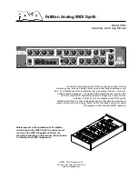
Page 2: ...2 IMPRINT MFB Ingenieurb ro Manfred Fricke Engineering office Neue Str 13 14163 Berlin Germany www mfberlin de...

Page 3: ...es for the use of electronic devices Please read all the notes Suitable location Only operate the device in closed rooms Never operate the device in humid environments Do not operate the device in dus...

Page 4: ...smooth cloth or brush for cleaning the device Do not use any alcohol solvents or similar chemicals These will damage the surfaces Proper use This device is exclusively intended for creating audio sig...

Page 5: ...ROGRAMMING 20 VELOCITY Routing 20 SYSTEM SETTINGS 22 Preset Selection 24 Saving Presets 24 Program Changes 24 SHIFT Functions 24 ARPEGGIATOR 26 SEQUENCER 28 Playing Sequences 28 Creating Sequences 28...

Page 6: ...corresponding socket on the unit s rear panel Find the corresponding on off switch alongside Make sure to connect the unit s AUDIO OUT to a mixing console an audio interface or an amplifier before swi...

Page 7: ...Y In VCO2 VCO2 VCO3 VCO3 VCO3 VCO1 Oscillator 1 offers an analogue ring modulator while oscillators 2 and 3 each utilize a digital ring modulator with so called XOR wiring which offers a rough soundin...

Page 8: ...ailable are Level pre mixer level modulation by LFO1 Pitch1 pitch modulation by LFO1 up to 2 octaves Pitch2 pitch modulation by LFO2 up to 2 octaves AD pitch modulation by envelope AD PWM modulation o...

Page 9: ...width center 75 VCO Synchronization All three oscillators of Dominion I can be hard synced Here the main oscillator will dictate its pitch to the synced partner Changing the tuning of the synced oscil...

Page 10: ...being modulated by VCO3 VCO1 2 are being modulated commonly by VCO3 FM Mod sets the amount resp intensity of the frequency modulation Use the six stage selector FM Mod Select to set a modulator for th...

Page 11: ...Ext In being used the noise generator will be replaced by an audio signal being fed in here The corresponding Noise Ext control will then set the level for the external audio signal The RM Y In contr...

Page 12: ...nd pass with 18 dB low pass and 6 dB high pass BP2 band pass with 12 dB low pass and 12 dB high pass BP3 band pass with 6 dB low pass and 6 dB high pass BP4 band pass with 6 dB low pass and 12 dB high...

Page 13: ...frequency The filter s resonance can either be modulated by LFO2 or envelope AD Use the Reso Sel switch to toggle between both modulation sources With the LED being lit LFO2 is used as modulation sour...

Page 14: ...ol the inversion of the envelope also applies to the oscillators modulation Envelope ADSR2 mainly controls the VCA and therefore sets the output volume of Dominion I However it may also serve to suppo...

Page 15: ...e whether the LFO waveform is restarted by every incoming MIDI note LED off free running LFO LED green free running LFO LED pulses in sync LED red green the LFO waveform cycle starts with each incomin...

Page 16: ...s the higher the modulation intensity This ribbon works equally to a common modulation wheel meaning it will remain at a certain position when the finger is being removed from the ribbon Activity is d...

Page 17: ...esets They are meant as performance tools only PITCH This ribbon works equally to a common pitch wheel meaning it will jump back to its original position as soon as the finger is being removed from th...

Page 18: ...by pressing Enter The display will now read O O O On n n n while the AT Select LED will turn off Available choices are pitch VCO Modulation and the filter s cutoff frequency OAP OAP OAP OAP pitch of a...

Page 19: ...lit red the envelopes will be retriggered by every new note even when played legato i e while the first key is still being held In normal mode LED off single trigger mode is active Glide The Glide co...

Page 20: ...ts These are the selector s positions VCA to ADSR All modulations are available simultaneously but with individual modulation amounts With a value of 00 00 00 00 being displayed no modulation is appli...

Page 21: ...R1 15 15 15 15 to 15 15 15 15 LFO affects the LFOs speeds 63 63 63 63 to 63 63 63 63 Use Enter to toggle between LFO1 left LED dot LFO2 middle LED dot and LFO3 right LED dot in the sub menu VCO affect...

Page 22: ...ly one note is being played For each additional note played an oscillator is being subtracted from the unison sound Glide type left LED dot t t t t C C C C the glide time is independent from the inter...

Page 23: ...ob positions Midi settings for channel local on off and dumps Sub menu 1 left LED dot MIDI channel 1 1 1 1 to 16 16 16 16 Sub menu 2 middle LED dot decoupling of keyboard and sound engine LOn LOn LOn...

Page 24: ...ory locations To do so press and hold Store choose a preset bank using Value when needed and select a memory location by pressing one of the buttons 1 to 8 The preset is stored upon release of the Sto...

Page 25: ...n these two buttons select the arpeggiator 1 ARP or sequencer 5 SEQ These are the only two function buttons to be mutually exclusive Buttons 2 3 and 4 envelope speeds The envelopes ADSR1 ADSR2 and AD...

Page 26: ...peggiator mode UNLATCH with UNLATCH being disabled every new note is being added to the arpeggio in Hold mode With UNLATCH being enabled using the SHIFT function a new chord will replace the previous...

Page 27: ...played on the keyboard rA1 rA1 rA1 rA1 to rA4 rA4 rA4 rA4 the arpeggio notes will additionally be repeated in one to five higher octaves Confirm edits by pressing Enter Shuffle Value shuffle factor Se...

Page 28: ...Creating Sequences To create an individual sequence press the Record button once first The display will now show the current resolution initial setting Scale16 16 16 16 which can be changed to your n...

Page 29: ...to transpose the sequence in real time use SHIFT Trans and the keyboard notes C1 to C3 Editing Sequences Existing sequences may be edited later Enter edit mode by pressing SHIFT and Record Scale EDIT...

Page 30: ...tandard With only one input being connected the signal will be distributed to the following VCOs By this connecting a single CV to input VCO1 allows control over all three oscillators pitches simultan...

Page 31: ...feed an audio signal into the Mixer replacing the noise generator see page 11 The corresponding level is set using the Mixer control Noise Ext The internal noise generator is being deactivated as soo...

Page 32: ...carry the waveform outputs of both LFOs for a possible modulation of external targets LFO2 In this input jack allows modulation of LFO2 s speed using an analogue control voltage ADSR1 Out ADSR2 Out AD...

Page 33: ...inion I on and off Midi IN Midi OUT Midi THRU these three connectors allow integration of Dominion I into a MIDI setup Sustain FSW connect a hold pedal closing type to this jack Audio OUT this jack ca...

Page 34: ...tion Control Change 1 64 T R o Mod Wheel Sustain Prog Change T R 0 127 System Exclusive T R o System Common Song Pos T R x Sel T R x Tune T R x System Realtime Clock T R x Commands T R x Aux Messages...

Page 35: ...ith these requirements provides a reasonable level of assurance that your use of this product in residential environment will not result in harmful interference with other electronic devices This equi...

Reviews: