Melco Bravo, Technical Manual
The Acqua Brevetti Bravo brings efficiency and reliability to your water purification needs. With its sleek design and advanced technology, this product ensures clean and pure water for your home or office. Enhance your experience by easily accessing the user manual through our manualshive.com, allowing you to download the Installation and Operating Instructions Manual for free.
Share
Download


Reviews:
No comments
Related manuals for Bravo

5002
Brand: Gamma Pages: 18

9002D
Brand: Janome Pages: 88

1118 Series
Brand: U.S. BLIND STITCH Pages: 32

120-17B
Brand: Adler Pages: 5

Windsor Chariot 3 iExtract 26 Duo
Brand: Kärcher Pages: 151

17U123
Brand: Singer Pages: 11

Sfera 6-36 R/F
Brand: Necta Pages: 19

GBC/VeloBind System Three Pro
Brand: Officezone Pages: 7

JUNO E1030
Brand: Janome Pages: 43

Smoke 400v3
Brand: Nebula Pages: 8

56416700
Brand: Nilfisk-Advance Pages: 54

Frozen Gourmet 455
Brand: Crane Pages: 57

DPK-5
Brand: SunStar Pages: 18
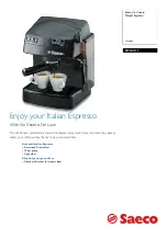
Saeco Via Veneto RI9345/11
Brand: Philips Pages: 2
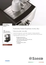
Saeco Poemia HD8325/79
Brand: Philips Pages: 2
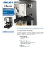
Saeco Poemia HD8325/47
Brand: Philips Pages: 3
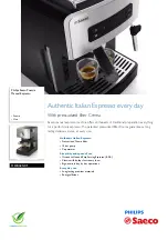
Saeco Poemia HD8425/01
Brand: Philips Pages: 3
XC-7500
Brand: Sony Pages: 92


