background image

This quick start guide explains how to quickly set up and activate your McAfee

®

 Network Security Platform NS7100,

NS7200, and NS7300 Sensors in in-line mode. These models have a throughput of 1.5 Gbps, 3 Gpbs, and 5 Gbps

respectively.

All product documentation referenced in this quick start guide is found on the McAfee ServicePortal.

The NS7100/NS7200/NS7300 Sensor model

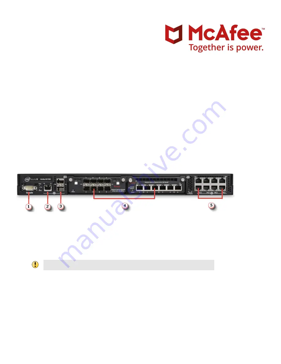
Figure 1  Sensor front panel

1

Console port (1)

2

RJ-11 port (1) for fail-open control of two built-in SFP+ ports in slot G0. The RJ-11 port supports 1 Gbps (SFP)

copper or fiber and 10 Gbps (SFP+) (SR and LR).

3

SFP+ 1/10 Gigabit Ethernet ports (2)

The RJ-11 port controls only the SFP+ 1/10 port pair in passive fail-open mode.

4

Two slots for I/O modules (Any combination of the interface modules can be used.)

SFP/SFP+ 1/10 GigE Monitoring ports (8)

RJ-45 10/100/1000 Mbps with internal fail-open Ethernet Monitoring ports (6)

10/1 GigE SM 8.5 micron with internal fail-open Monitoring ports (4)

10/1 GigE MM 50 micron with internal fail-open Monitoring ports (4)

10/1 GigE MM 62.5 micron with internal fail-open Monitoring ports (4)

5

RJ-45 10/100/1000 Mbps Ethernet Monitoring ports (8)

NS7x00 Quick Start Guide

Revision D

McAfee Network Security Platform

1

Summary of Contents for NS7100

Page 1: ...ort supports 1 Gbps SFP copper or fiber and 10 Gbps SFP SR and LR 3 SFP 1 10 Gigabit Ethernet ports 2 The RJ 11 port controls only the SFP 1 10 port pair in passive fail open mode 4 Two slots for I O modules Any combination of the interface modules can be used SFP SFP 1 10 GigE Monitoring ports 8 RJ 45 10 100 1000 Mbps with internal fail open Ethernet Monitoring ports 6 10 1 GigE SM 8 5 micron wit...

Page 2: ...rt R1 1 5 RJ 45 10 100 1000 Management port Mgmt 1 1 Verify the contents in the box The following accessories are shipped in the NS7x00 Sensor crate Sensor Power cords McAfee provides standard and international power cables Set of rack mounting rails Printed Quick Start Guide 2 Verify the hardware and software requirements Make sure to meet the following hardware requirements For more information ...

Page 3: ...perating system Windows Server 2012 R2 Datacenter Edition Server with a GUI English operating system Windows Server 2012 R2 Datacenter Edition Server with a GUI Japanese operating system Only X64 architecture is supported Same as the minimum required Memory 8 GB 8 GB or more CPU Server model processor such as Intel Xeon Same Disk space 100 GB 300 GB or more Network 100 Mbps card 1000 Mbps card Mon...

Page 4: ...Install the slide rails and rack mount the Sensor McAfee recommends rack mounting your Sensor For maintenance purposes you must have access to the front and rear of the Sensor Before you mount the Sensor on the rack make sure that the power is off Remove the power cable and all network interface cables from the Sensor Due to the weight of the appliance McAfee recommends that two people place the c...

Page 5: ... on chassis unit b Use screws to secure inner members in place Apply to both sides of chassis unit c Mount the slide cabinet sections to the rack a Install the front end of each slide cabinet section to the rack using the slide tool less features The tool less latch rotates when the bracket is pressed up against the rack rails b Align adjust and attach the rear brackets to the rack rail 5 ...

Page 6: ...With the chassis unit in a fully closed position secure using two truss head screws b Drive the screws through the inner member flange and through the rack rails The screws thread directly to the cabinet slide members Tighten the screws 4 Install the interface modules You can purchase the following interface modules and insert them into the relevant slots on your NS7x00 Sensor 8 port SFP SFP 1 10 ...

Page 7: ...e module using your thumb and forefinger and insert it into the modular bay c Drive in the screws fixed on the sides of the module to attach it to the Sensor 5 Connect the Management and Console ports a On the rear panel of the NS7x00 Sensors plug a Category 5e Ethernet cable in the Management port labeled Mgmt b Plug the other end of the cable into the network device connected to your Manager ser...

Page 8: ...rectly connect to the console for initial configuration you cannot configure the Sensor remotely Terminal servers are provided for console access The required settings for Hyperterminal are Baud rate 115200 Stop Bits 1 Number of Bits 8 Control Flow None Parity None e Plug one end of the power cable into the power inlet and plug the other end into a power source The Sensor ships with standard US po...

Page 9: ...ministrator rights on the target Windows Server to install the Manager software A MySQL database is included with the Manager and is installed embedded automatically on your target Windows Server during this process The following steps briefly explain the Manager installation a Prepare the system according to the requirements outlined in McAfee Network Security Platform Installation Guide and the ...

Page 10: ...ces then click New You do not require a license file to enable IPS on NS series Sensors The Add New Device page is displayed We recommend using the Add Device wizard to add a device d Enter the following mandatory information in the appropriate fields 1 Device Name The Sensor name must begin with a letter The maximum length of the name is 25 characters 2 Device Type Specifies the type of device to...

Page 11: ...er 4 Updating Mode Select Online or Offline Selecting Offline enables Offline Sensor update Online is the default mode e Click Save The added Sensor is displayed on the Add and Remove Devices page 10 Configure Sensor information Configure the Sensor with the network information a name and the shared secret key that the Sensor uses to establish secure communication with the Manager Use the name and...

Page 12: ... as the Manager set the address of the default Gateway At the prompt type set sensor gateway A B C D Example set sensor gateway 192 168 3 68 f Set the IP address of the Manager server At the prompt type set manager ip A B C D Example set manager ip 192 168 2 8 g Set the IP address and subnet mask of the Sensor At the prompt type set sensor ip A B C D E F G H Example set sensor ip 192 168 2 12 255 ...

Page 13: ...lue matches the shared secret key value you provided in the Manager interface in Step 9 Add the Sensor to the Manager k To verify the configuration information type show Check that all information is correct l To exit the session type exit 11 Verify successful installation a In the Sensor CLI type status The status report is displayed The Sensor parameter System Initialized must be yes and for Man...

Page 14: ...ion If any attack in the policy is triggered the Sensor automatically blocks the attack To tune this or any other McAfee provided policies you can clone the policy and then customize it as described in the McAfee Network Security Platform IPS Administration Guide e Click Devices Device_Name Setup Physical Ports f Select the port on the Sensor that you cabled to view port settings Make sure that yo...

Page 15: ...hreat Analyzer to view alert statistics as attacks are detected A summary of alerts is displayed in the Unacknowledged Alert Summary area of the Manager Dashboard page c Having problems See the McAfee Network Security Platform Troubleshooting Guide for troubleshooting information d Most deployment problems stem from configuration mismatches between the Sensor and the network devices to which it is...

Page 16: ...Afee LLC McAfee and the McAfee logo are trademarks or registered trademarks of McAfee LLC or its subsidiaries in the US and other countries Other marks and brands may be claimed as the property of others 16 700 4423D00 ...

Reviews: