


INSTALLATION OPERATION MAINTENANCE
THIS MANUAL MUST BE KEPT ON BOARD AT ALL TIMES
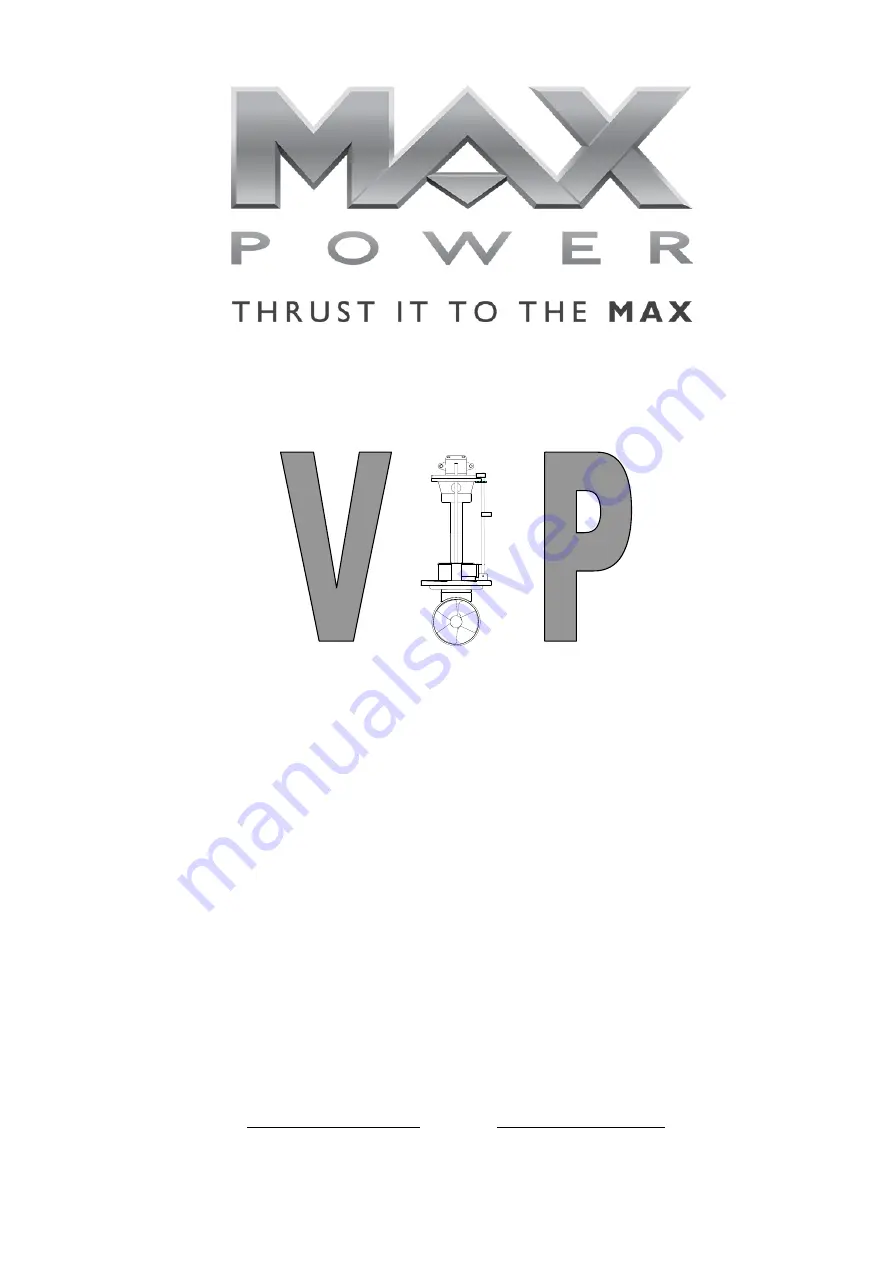
VIP 150 HYDRAULIC
Serial Number:..............................................
Date of Installation:.......................................
Via Philips 5, 20900 Monza (MI), Italy
Tel.:
+30 039 200 1973-936 Fax: +39 039 2004299
www.max-power.com
e-mail:[email protected]


