background image

COSEC COGNIFACE INTEGRA

Safety Instructions

These instructions are intended to ensure that the user can
use the product correctly to avoid danger or property loss.

Do not install the device:

On unstable surface.

Where ferromagnetic field or noise is induced.

Where static is created, such as desks made of plastics, 
carpets.

Near volatile inflammable materials or inflammable goods such 
as drapes.

Where volatile gas and/or inflammable gas is created.

Cautions

Installing and servicing should be done only by qualified 
technician. 

There are no user-serviceable parts inside.

Opening or removing the device cover may result in electric 
shock or exposure to other hazards.

Use the device only for the purpose for which it was designed.

Warning

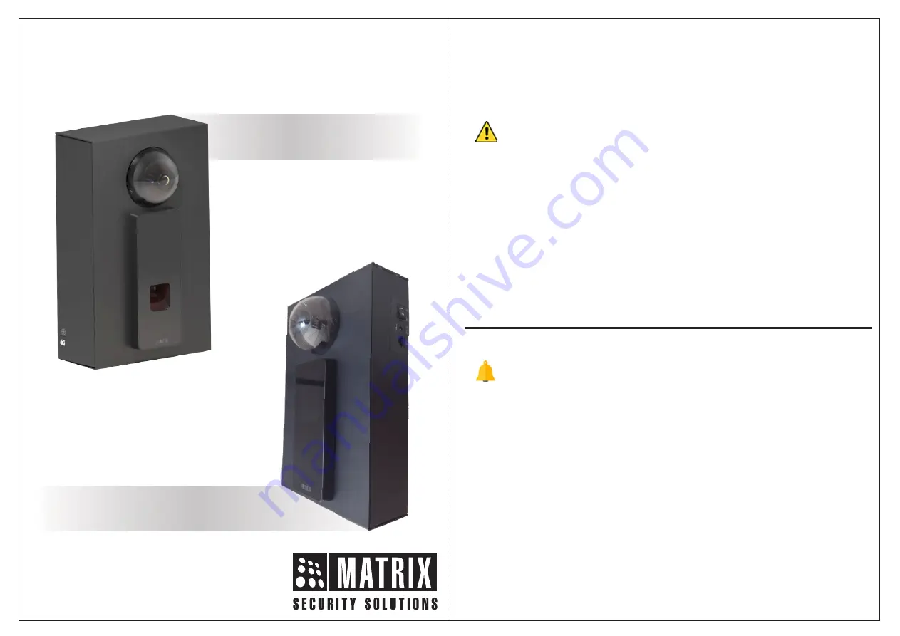
COGNIFACE INTEGRA100

COGNIFACE INTEGRA200

11.19"

Summary of Contents for COSEC COGNIFACE INTEGRA200

Page 1: ...as desks made of plastics carpets Near volatile inflammable materials or inflammable goods such as drapes Where volatile gas and or inflammable gas is created Cautions Installing and servicing should be done only by qualified technician There are no user serviceable parts inside Opening or removing the device cover may result in electric shock or exposure to other hazards Use the device only for t...

Page 2: ...cesscontrol com Know your COGNIFACE INTEGRA A COSEC COGNIFACE INTEGRA is an enclosure box which helps in maintaining hardware elements to encourage Face Recognition feature for Time and Attendance module through Matrix Devices Here a COSEC device is integrated with IP Camera for Face Recognition efficiently It is available in two models COGNIFCAEINTEGRA100andCOGNIFCAEINTEGRA200 4 4 Know your COGNI...

Page 3: ... follows 6 For providing efficient Face Recognition IP Camera is used to capture user s image accurately In COGNIFACE INTEGRA Matrix IP Camera is used Refer Figure 3 It is a Standard 2MP Dome Camera with Focal length of 2 8mm mounted above COSEC ARGO device at a suitable height in COGNIFACE INTEGRA It captures user image from the best angle The captured image is used to identify users for Time and...

Page 4: ...s is created where ferro magnetic field or noise is induced where static is created such as desk made up of plastic or carpet 5 Do not expose the device to extreme weather condition Preparing for Installation Installation Process is same for both the COSEC COGNIFACE INTEGRA models Before Wall Mounting COSEC COGNIFACE INTEGRA follow the instructions given below Connecting Earthing Cable Remove the ...

Page 5: ...lid of battery compartment by unscrewing four screws with the help of screw driver Keep those screws aside carefully because they will be required to fix the lid of battery compartment back into its position once the battery cells are inserted Open the Battery Compartment as shown in Figure 5 9 10 Figure 5 Figure 6 ...

Page 6: ...nting 1 Key Slot Mounting 2 Through Slot Mounting Close the lid of the battery compartment as shown in Figure 7 and tighten those four screws back into their position with the help of screw driver as shown in Figure 8 In case of power cut this will provide battery back up for minimum 2 hours 11 12 Figure 7 Figure 8 The Key Slot Mounting is recommended due to less complexity ...

Page 7: ...nting 1 Place the mounting template against the wall where Installation is to be done Trace four screw holes using mounting template with pen pencil as shown in the Figure 9 and Figure 10 below 14 13 Figure 9 Figure 10 70 279 282 109 123 146 ...

Page 8: ...w holes A B C D along the traced markings with the help of power drill as shown in Figure 11 below 3 Fix the supplied screw grips into the A B C and D screw holes as shown in the Figure 12 A D B C Figure 11 Figure 12 A D B C ...

Page 9: ...4 Insert screws into screw holes A B C and D having screw grips as shown in the Figure 13 and Figure 14 A D B C A D C B 17 18 Figure 13 Figure 14 ...

Page 10: ...A D B C 19 20 5 Align Key hole slots of COSEC COGNIFACE INTEGRA with the screws A B C and D on the wall and slightly slide it downwards as shown in Figure 15 and Figure 16 Figure 15 Figure 16 ...

Page 11: ...l as shown in the Figure 9 and Figure 10 2 Drill those four screw holes A B C D along the traced markings with the help of power drill as shown in Figure 11 3 Fix the supplied screw grips into the A B C and D screw holes as shown in the Figure 12 4 Now unscrew the COSEC ARGO Device as shown in Figure 17 22 21 Figure 17 Screw 5 Detach the Ethernet Cable and the DC Jack Cable of COSEC ARGO Device se...

Page 12: ...gure 19 7 Unscrew the eight screws present on the Top Enclosure of the Device as shown in Figure 20 1 2 3 4 5 6 7 8 Figure 20 6 Remove the COSEC ARGO Device as shown in Figure 19 and keep it aside with caution ...

Page 13: ...osure as shown in Figure 21 Figure 21 9 Fix the four screws in the through slots of bottom enclosure Tighten screw 1 in screw hole A screw 2 in screw hole B screw 3 in screw hole C and screw 4 in screw hole D with the help of screw driver as shown in Figure 22 1 2 3 4 Figure 22 DC Jack Cable Ethernet Cable ...

Page 14: ...ure 23 Tighten those 8 screws back with the help of screw driver 11 Before placing the ARGO Device back into its position remember to plug in the Ethernet Cable and the DC Jack Cable correctly Now tighten the screw present at the bottom of the COSEC ARGO Device to fix it back into its position see Figure 24 Figure 23 Figure 24 ...

Page 15: ...RGO door to the users Ensure that COSEC ARGO Door FR Module and IP Camera are in the same subnet 3 On ARGO Door Device Configuration page select the Capturing device as IP Camera in Video Surveillance section Configure the MJPEG URL of IP Camera in Advance Settings 4 For configuring FR Settings on ARGO Door go to Identification Server in Device Configuration page of ARGO Enable FR and select FR Mo...

Page 16: ...y not cause harmful interference 2 This device must accept any interference received including interference that may cause undesired operation This equipment has been tested and found to comply with the limits of Class A digital device pursuant to part 15 of the FCC Rules These limits are designed to provide reasonable protection against harmful interference when the equipment is operated in a com...

Reviews: