Specifications
Functional
Paper Weight . . . . .18# Bond (67.72gsm) min., 90# Index (161.78gsm) Max.
Max Paper Size . . . . . . . . . . . . . . . . . . . . . . . . . . . . . . . . . .12" W x 18" L max.
Min Paper Size . . . . . . . . . . . . . . . . . . . . . .2.5" W x 5.2" L min. (half fold only)
Speed . . . . . . .5000 - 12,000 sheets per hour (8 ½" x 11" sheets, Letter fold)
*Speeds may vary because of different paper lengths & fold types
Types of Folds . .Letter, Zee, Half, Double Parallel, Gate, Engineering, Church
Fold Length . . .2.3" (5.8 cm) min., 14.75" (37.5 cm) max., for both fold tables
Paper Capacity . . . . .500 sheets of 20# Bond paper (75 gsm), or a 2¼" stack
Sheet Capacity (Stapled) . . . . . . . . . . . . . . . . . . .4 sheets of 20# bond typical
Feed Method . . . . . . . . . . . . . . . . . . . . . . . . . . . . . . . . . . . . .Top Feed, Friction
Physical
Dimensions . .43.2" (110 cm) Wide x 17.8" (452 cm) High x 22.2" Deep (564 cm)
Shipping Weight . . . . . . . . . . . . . . . . . . . . . . . . . . . . . . . . . . . . . . . . . .102 lbs.
Electrical
Power . . . . . . . . . . . . . . . . . . . . . . . . . . . . . . . . . . . .115 V, AC, 1,4 A, 50/60Hz
Optional . . . . . . . . . . . . . . . . . . . . . . . . . . .220/230 V.A.C., .8 Amps, 50/60 Hz
WARNING! Never connect power to the machine until you are ready to set
up and operate the folder. This machine contains moving parts. During
setup, operation, and maintenance keep hands, hair, loose clothing, and
jewelry away from all moving parts. Serious bodily injury could result.
Notice: This folder contains NO USER SERVICEABLE COMPONENTS.
Service or disassembly should only be completed by a qualified techni-
cian, and with the power disconnected and locked out. The AC outlet for
this machine must be near by, and access to the outlet must not be
blocked.
1812 AutoFolder
Set-up Instructions
X
Getting Started (Installation)
P
ower Connection
The Power Cord plugs into the Power
Connection on the folder. Please note the loca-
tion of the power switch and fuseholder at this
time, which are located on the same surface as
the power connection, nearest the front of the
folder.
Fold Tables
Both fold table assemblies are the same, and can be installed into either the first or sec-
ond fold table positions.
Fold Table Installation
To install the 1st Fold Table, refer to the illustration below. Step 1: slide the front
slot opening of the fold table onto the inner set of pins (closest to the folding
rollers). Step 2: lower the fold table onto the outer set of pins with a light
amount of downward pressure as shown. There will be a slight snapping action
as the fold table drops into the detent position. Repeat Step 1 and Step 2 for
2nd Fold Table installation.
Table Extension
Your folder comes with two Table Extensions. One is used as an extension on
the Exit Conveyor, the other on the Feed Table (see illustration at right).
To install the Extension onto the Feed Table, align the
locking tabs of the Extension with the slots in the Feed
Table as shown. Squeeze the Feed Table and
Extension together nearest the tabs and slots until the
2 pieces snap together.
Power Connection
Power Switch
Installing table extensions (cont.)
To install the Extension onto the Exit Conveyor, align the
tabs on the Extension with the slots provided in the Exit
Conveyor as shown. No force is required to install the
Extension - gravity will hold the Extension in place.
X
Using Your Folder
Reach under the second fold table and turn on the power. When the power
switch is turned on the green power LED will illuminate.
Loading Paper
To load paper into the Feed Table, firmly push the Feed Table down, until it locks
into the "load" position as shown.
Load the paper into the Feed Table, making sure that the paper is fully within the
folder, and that the leading edge of the stack is resting against the face indicated
below. Once the Feed Table has been loaded with paper, the Feed Table must
be unlocked, allowing the Feed Table to return to the raised position. To unlock
the Feed Table, press the Feed Table Release (see illustration below).
Setting the Paper Guides
If your paper size is different than the factory set paper size, adjust the Paper Guides
to the desired size. To adjust the paper guides, loosen the thumb knobs of the Paper
Guides located under the Feed Table. Lay a small stack of paper against the
locked Paper Guide. Slide the opposite Paper Guide up to the paper and lock it
in place. Leave a small gap, about 1/64” (.4mm) between the paper and guides
to allow easier paper feeding. Do not over-tighten the thumb knobs!
NOTE: too much gap will cause inconsistent or crooked feeding.
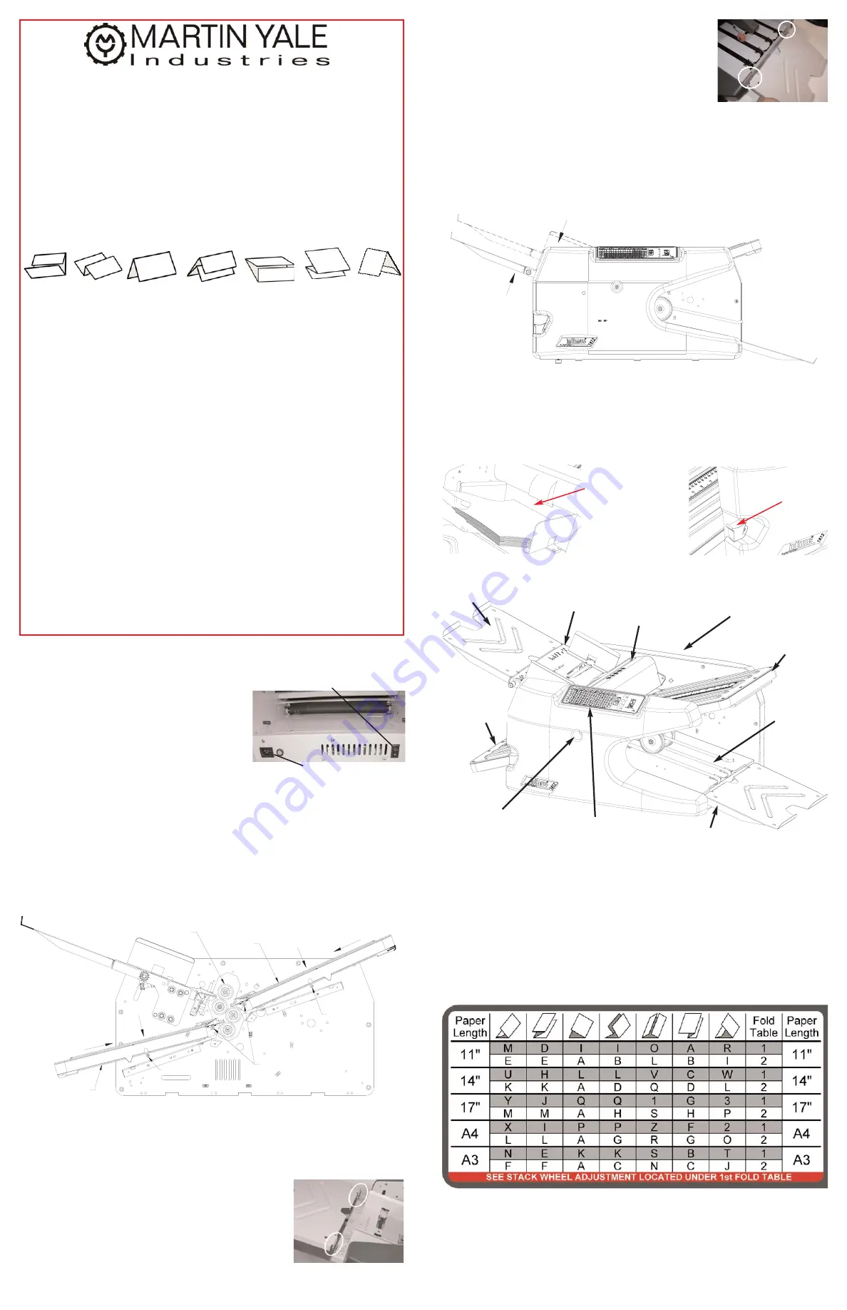
Setting a Fold Type
Use the following directions, along with the Folding Chart (see illustration above)
to create all types of folds. The Folding Chart is located on the Operator
Interface for quick reference.
1. Loosen the Fold Table Thumb Knob on the 1st Fold Table Assembly and
move the Paper Stop to the appropriate circle according to the Folding Chart.
Retighten the Fold Table Thumb Knob.
OUTER PIN
INNER PINS
OUTER PIN
STEP 1
STEP 2
STEP 1
STEP 2
1ST FOLD
TABLE
2ND FOLD
TABLE
FOLDING
ROLLERS
PUSH HERE ON FEED TABLE
TO LOCK INTO LOAD POSITION
LOAD POSITION
Stack must
rest
against
this face!
Feed
Table
Release
Parts
Feed Table
Extension
De-jam Port
Operator Interface
Exit
Conveyor
1st Fold
Table
Multi-Sheet
Bypass
De-jam Handle
Storage
2nd Fold
Table
Extension
Folding Chart