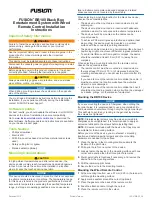
background image


Electronic Compass Indicator  ECS1 

CD110


COMPASS display


CD110

-REV. 1.3   20-12-2004

Summary of Contents for CD110

Page 1: ...Electronic Compass Indicator ECS1 CD110 COMPASS display CD110 REV 1 3 20 12 2004 ...

Page 2: ...4 1 7 Align ST7 6 4 1 8 Variation ST8 6 4 1 9 Error messages 6 5 Installation 7 5 1 Mechanical 7 5 2 Connections 7 6 CD110 Specifications 7 6 CD110 Specifications 8 6 1 Hardware 8 6 2 NMEA0183 messages 8 6 3 Bluetooth optional 9 6 4 NMEA2000 optional 9 6 5 Certifications 9 7 Overall dimensions 9 7 Overall dimensions 10 7 1 Drill pattern 10 7 2 Outside dimensions 10 8 Wiring diagrams 11 8 1 pin ass...

Page 3: ...e CD110 display x Heading on electronic compass rose x Heading on 7 segment display x True North or Magnetic North x Damping x Variation x Alignment x Off course alarm 1 1 Package contents x CD110 x 2 female 6 pole connectors x 1 female 4 pole connectors x Mounting seal x 4 metal rings M4 screwnuts x Drill Template x Quickstart instruction leaflet Compass Display CD110 1 ...

Page 4: ...you press the SET button for more than 2 seconds you will exit the menu x Down on off setting for the off course alarm or when in a menu it works as a button to select a menu or change settings x Up select true or mag north when in a menu it works as a button to select a menu or change settings The function of a button is activated when the button is released both UP and DOWN buttons have an autom...

Page 5: ...s 7 settings x Level 1 x Level 2 x Level 3 x Level 4 x Level 5 x Remote x Off If the remote setting is chosen the brightness of the backlight will be set by a voltage applied to the backlight pin on the connector See Connections for pin information Before you can use the alarm you have to set the values These have to be set by entering the Course alarm menu ST1 If the alarm is on the alarm indicat...

Page 6: ...oard alarm boundary with the up down buttons This can be set from 2 to 45 degrees difference If the Set course is 246 the Limit portside set to 3 and the Limit starboard is set to 2 then the alarm will sound if the course change is smaller than 246 3 243 and if the course is higher than 246 2 248 degrees Use the down button in the default view to set the Alarm ON OFF see 3 4 4 1 2 Damping ST2 Damp...

Page 7: ...lect the ST4 menu Press SET to enter the menu and now you can choose ON or OFF by pressing the up down buttons x Press SET short to enter the selected value or x Press the Light button to reset the value to default ON or x Keep SET pressed for two seconds to exit to the default view 4 1 5 Contrast ST5 Press SET and use the up button to select the ST5 menu Press SET to enter the menu and now you ca...

Page 8: ...press SET once or keep SET pressed for two seconds to exit to the default view 4 1 8 Variation ST8 The Variation can be set to compensate the magnetic heading so that the display shows the geograpical True heading x Press SET and up down to select the Variation menu ST8 Press SET to enter the menu Use the up down buttons to set the offset This can be set in steps of 0 1 up to 45 To exit the menu p...

Page 9: ...seal fits correctly between the meter and the panel or bulkhead 5 2 Connections For wiring diagram see chapter 8 Connect the cable from the compass sensor as shown in the diagram If you need to cut and rejoin the cable be sure to connect colour to colour The CD110 display is suitable for both 12 and 24 Volt DC Connect the power supply as per diagram See chapter 8 for the optional connections Compa...

Page 10: ...ive standard message HCHDG X X Y Y v Z Z Q CC 13 10 X X compass heading Y Y v not used Z Z variation Q variation available a or invalid v CC Checksum field 13 carriage return 10 line feed Checksum The checksum is the last field in a message and follows the checksum delimiter character The checksum is the 8 bit exclusive OR no start or stop bits of all characters in the message including delimiters...

Page 11: ...mand Acknowledgment Group function PGN 59392 Acknowledgment PGN 59904 Request PGN 60160 Transport Protocol Data Transfer PGN 60416 Transport Protocol Connection Management PGN 60928 Address Claim PGN 126996 Product information PGN 126464 Transmit Receive PGN List Group Function PGN 127250 1 SID Sequence ID INT8 unsigned 2 Heading Sensor Reading INT16 unsigned 3 Deviation INT16 signed Not used 4 Va...

Page 12: ...7 Overall dimensions 7 1 Drill pattern included on separate sheet 7 2 Outside dimensions Compass Display CD110 10 ...

Page 13: ...tput 7 GND 8 NMEA0183 echo of NMEA input pin 15 and 16 9 Not used 10 12V 24V Battery power input use power switch and 500mA fuse 11 Battery GND 12 Alarm output max 100mA open collector 13 NMEA0183 gnd 14 NMEA0183 out 15 NMEA0183 INA 16 NMEA0183 INB OUTPUT INPUT 1 2 3 4 5 6 7 8 9 10 11 12 13 14 15 16 NMEA in NMEA in SHIELD Backlight Dim input fuse 12 24 V Compass Display CD110 11 ...

Page 14: ...ssages from the compass sensor PIN 8 NMEA0183 output in combination with GND pin 7 8 2 3 Alarm output The Alarm output is used for connecting an external warning device such as a buzzer If more than 100 mA is needed a small relay should be used PIN 12 Alarm output in combination with the battery pin 8 3 Service menu To enter the service menu you have to press SET when you switch the power on 8 3 1...

Page 15: ......

Reviews: