background image

PRODUCT

P 1/ 14

T

ECHNICAL INFORMATION

Models No.

 Description

C

ONCEPT AND MAIN APPLICATIONS

S

pecification

S

tandard equipment

O

ptional  accessories

TD0101, TD0101F

Impact Driver

Phillips bits, Square bits, Socket bits, Drill chucks, Hex shank auger bits,
Bit piece, Adjustable locator

Models TD0101 and TD0101F are cost-competitive
100N.m-class impact driver developed as the entry model
of Makita impact driver series.
Its main features are:
    Compact design with an overall length of 184mm (7-1/4")
    Lightweight at only 0.99kg (2.2lbs)

The only difference between TD0101 and TD0101F is:
    TD0101: Without LED job light
    TD0101F: With LED job light    

Note: The standard equipment for the tool shown above may differ by country.

Phillips bit .........................  1 pc
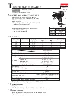
Dimensions: mm (")

Width (W)
Height (H)

Length (L)

184 (7-1/4)

TD0101, TD0101F

67 (2-5/8)

192 (7-9/16)

L

H

W

Continuous Rating (W)

Voltage (V)

Cycle (Hz)

Input

Output

90

Max. Output (W)

110
120
220
230
240

2.2
1.7
1.1
1.0
1.0

50/60
50/60
50/60
50/60
50/60

230

---

230
230
230

140
140

140
140

140

Current (A)

90
90
90
90

0 - 3,200

6.35 (1/4) Hex

0 - 3,600

No load speed: min

-1 

= rpm

TD0101/ TD0101F

Specifications

Model

Driving shank: mm (")

100 [1,020] (885)

Max. fastening torque*: N.m [kgf.cm] (in.lbs)

Yes

0.9

9

 (2.2)

Reverse switch

No/ Yes

LED job light

No

Yes

Electric brake
Variable speed control by trigger

Net weight: kg (lbs)

0.9

9

Weight according EPTA-Procedure 01/2003: kg

Impacts per min.: min-

1

=ipm

Capacities

Standard bolt
High tensile bolt

Machine screw

M5 - M14 (3/16 - 9/16")

M5 - M10 (3/16 - 3/8")

Coarse thread screw

22 - 90mm (7/8 - 3-1/2")

M4 - M8 (5/32 - 5/16")

Power supply cord: m (ft)

Australia, New Zealand, Brazil, Chile: 2.0 (6.6)

Other countries: 2.5 (8.2)

Protection against electric shock

Double insulation

*torque at 3 seconds after seating when fastening M12 high tensile bolt

Summary of Contents for TD0101

Page 1: ...4 7 1 4 TD0101 TD0101F 67 2 5 8 192 7 9 16 L H W Continuous Rating W Voltage V Cycle Hz Input Output 90 Max Output W 110 120 220 230 240 2 2 1 7 1 1 1 0 1 0 50 60 50 60 50 60 50 60 50 60 230 230 230 2...

Page 2: ...ng S and R pliers Disassembling Assembling Ring spring 10 1R346 Center attachment for 1R045 134844 7 Socket 27 50 Disassembling Hammer case complete Description Use for Item No Apply Makita grease FA...

Page 3: ...of Hammer case complete slide Hammer case cover toward Bit sleeve side Hammer case cover can be removed from Hammer case complete Remove bumper Separate Hammer case section from Motor section hook Bit...

Page 4: ...041 flat portions Bearing box Hammer case complete Hold the flat portion of Hammer case complete in vise with 1R041 Hammer case complete can be disassembled as illustrated below Vise 134847 1 Attach 1...

Page 5: ...he assembled Hammer case complete in the same position as disassembling And assemble as illustrated in Fig 6 Fig 6 3 Join Motor section with Hammer case complete And assemble them to Housing set L Ref...

Page 6: ...eeve Sleeve Hammer Case Complete Anvil Use 1R232 for stabilizing Sleeve in the position where Ring spring 11 can be easily removed 1R232 Ring spring 10 Fig 8 Fig 9 Fig 10 Steel ball 3 2psc Compression...

Page 7: ...lure to follow this instruction could cause Steel balls to get out of hammer Fig R Fig F 1 Press down Hammer using 1R045 to align the opening for Steel ball insertion with the top of cam grooving on S...

Page 8: ...BLING Take the disassembling step in reverse Note Make sure that the place equivalent to one piece of Steel ball 3 has to be in Hammer when all 24 pieces of Steel ball 3 are set in place Refer to Fig...

Page 9: ...viewed from Brush holder side The above illustrated Field and Switch are viewed from Brush holder side Housing set left side Housing set right side Noise suppressor Noise suppressor and Line filter ar...

Page 10: ...s Wiring around Holder arm Rib Rib Rib Fix Field lead wires red clear with lead wire holders on Switch Rib Power supply cord Lead wire orange of left Brush holder Wiring of Lead wire orange of left Br...

Page 11: ...e countries White lead wire is used for some countries White lead wire is used for some countries Brush holder Switch LED Circuit Brush holder Field Housing set left side Housing set right side Noise...

Page 12: ...der on Switch Lead wire orange of left Brush holder Wiring of Lead wire orange of left Brush holder and Field lead wire white Guide Lead wire orange of left brush holder by Ribs Guide field Lead wire...

Page 13: ...d Field and Switch are viewed from Brush holder side Power supply cord This Lead wire is black for some countries This Lead wire is white for some countries Brush holder Switch LED Circuit Brush holde...

Page 14: ...ack to LED circuit Holder arm rib of Holder arm Wiring of Field lead wires Fix Field lead wire red with Lead wire holders on Switch rib Field lead wire white Lead wire holder on Switch Lead wire orang...

Reviews: