background image

Summary of Contents for 2030S

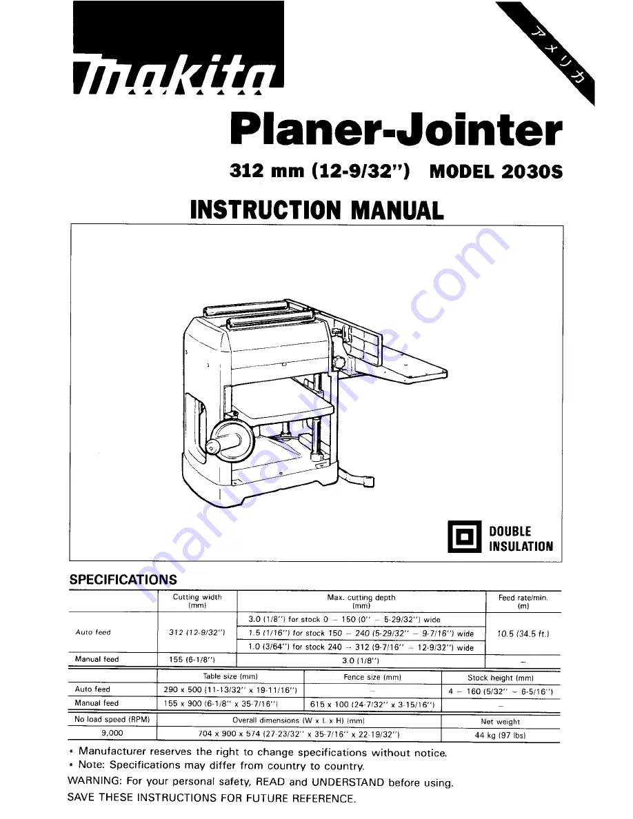
Page 1: ...or stock 150 240 15 29 32 9 7 16 wide 1 013 64 for stock 240 312 9 7116 12 9 32 wide 312 12 9 32 1 10 5 34 5ft 1 155 16 1 8 1 3 0 118 Table size lmml Fence size mml Stock height lmml 290 x 500 I1 1 13 32 x 19 11 16 4 160 15 32 6 5 16 155 x 900 6 118 x 35 7116 615 x 100 124 7132 x 3 15116 Net weight 44 kg 197 lbsl Overall dimensions W x L x HI lmml 704 x 900 x 574 27 23132 x 35 7116 x 22 19132 DOUB...

Page 2: ...ys 8 DON T FORCE TOOL It will do the job better and safer at the rate for which it was designed 9 USE RIGHT TOOL Don t force tool or attachment t o do a job for which it was not designed IO WEAR PROPER APPAREL Wear no loose clothing gloves neckties rings bracelets or other jewelry which may get caught in moving parts Nonslip footwear is recommended Wear protective hair covering to contain long hai...

Page 3: ...sk of injury t o persons 19 NEVER STAND ON TOOL Serious injury could occur if the tool is tipped or if the cutting tool is accidentally contacted 20 CHECK DAMAGED PARTS Before further use of the tool a guard or other part that is damaged should be carefully checked to determine that it will operate properly and perform its intended function check for alignment of moving parts binding of moving par...

Page 4: ...terhead covers 6 Remove nails and clean the workpiece before cutting Nail sand or other 7 Make sure the blade is not contacting workpiece before the switch is turned 8 Wait until the blades attain full speed before cutting 9 Keep hands away from rotating parts cracked or damaged blades immediately operating at the same time matter can cause blade damage on IO Stop operation immediately if you noti...

Page 5: ... blocks jigs fixtures stops and the like FOR AUTO PLANER 1 Two or more pieces of narrow but similar thickness stock can be passed through the auto planer side by side However allow some spacing between the stock to permit the feed rollers to grip the thinnest piece Otherwise a slightly thinner piece could be kicked back by the cutterhead 2 Determine the depth of cut according t o the table shown o...

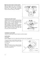
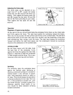
Page 6: ...e When locating it without bolting use the stays provided to help maintain its stability Remove the two bolts which secure the stays Extend the stays by one bolt hole and secure them using the bolts Installing the crank handle Install the crank handle using the socket wrench provided Switch action CAUTION Before pluggingin the tool always be sure that the tool is switched off To start the tool ins...

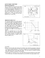
Page 7: ...amage To adjust the depth of cut proceed as follows Insert the workpiece flat on the infeed table top Raise the table by turning the crank handle clockwise The depth gauge will rise and the amount of gauge rise indi cates the depth of cut I S c a l e Indicator plate I Crank h a n d l e d 3 mm 1 18 s d 1 1132 l Max demh of cut 150 16 I Width nm 132 l Scale7 Indicator plate CAUTION Always raise the ...

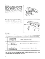
Page 8: ...table side This is especially convenient with two operators 115mm 4112 I Having grooves at intervals of 1 1 5 mm 4 1 2 Roller CAUTION e Workpieces with the following dimensions cannot be fed into the auto planer because the interval between the two feed rollers is 114 mm 4 1 2 Do not try to cut them I I 1 1 Fq 1 Less than I 1 5 mm 4 1 2 long Less than 1 1 5m m I More than 1 1 5 mm 4 1i2 I Having a...

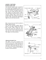
Page 9: ...e extension support table as follows First fold the extension support table as shown in the figure Tighten the two hex bolts securely While holding the legs loosen the screws and unhook the arms from the screw Fold the legs and hook the arms over the screw using the hook 6 Then tighten the screws securely Adjusting the depth of cut The depth of cut can be adjusted from 0 mm to 3 mm 1 8 Align the p...

Page 10: ...nce The right hand presses the workpiece forward and before the right hand passes over the cutterhead it should be cautiously moved to the workpiece on the outfeed table Jointing an edge Set the fence square with the table Hold the best fece of the workpiece firmly against the fence throughout the feed Side pressure is required to keep the workpiece in flush contact with the fence This is very imp...

Page 11: ...uggedbefore removing or installing the blades 0 Handle the blades very carefully when removing or installing the bladesto prevent cuts or injury from the blades and to prevent damage to the blades They are razor sharp 0 Clean out all chips dust pitch or foreign matter adheringto the drum or blades before installing the blades 0 Use blades of the same dimensionsand weight or drum oscillation vibrat...

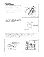
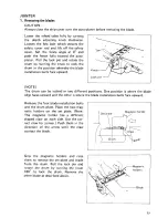
Page 12: ...for auto planer Knob 1 Hex bolt Blad installation bolt For jointer Claw MMagnetic holder I Place the two magnetic holders on the set plate and push them in the direction of the arrow until the claw contacts the blade Remove the eight blade installation bolts using the socket wrench Grip the magneticholders and raise them straight up to remove the set plate and blade from the drum Pressthe lock pla...

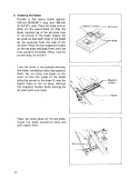
Page 13: ...tic holders on the set plate and push them until the claw contacts the blade Note Use the correct claw for auto planer Grip the magnetic holders and slip the heel of the set plate into the groove in the drum Install the blade installation bolts After tightening all the blade installa tion bolts lightly and evenly from the center to the outside tighten them com pletely following the same sequence R...

Page 14: ...cure using the hex bolt CAUTION 0 Do not tighten the blade installation bolts without the blade locating lug of the set plate correctly resting in the groove of the blade This may cause damage to the blade and potential injury to the operator Do not turn the tool on with the chip cover open 0 Tighten the blade installation bolts securely when installingthe blades 14 ...

Page 15: ... upward Lock pin NOTE The drum can be locked in two different positions One position is where the blade edge faces upward and the other is where the blade installation bolts face upward Remove the four blade installation bolts and the drum plate Place the two mag netic holders on the set plate Note The magnetic holder has a different shaped claw on each side Use the cor rect claw for jointer Push ...

Page 16: ...e Place the two magnetic holders on the set plate and push them until the claw contacts the blade Note Use the correct claw for jointer Lock the drum in the position whereby the blade installation bolts face upward Place the set plate and blade on the drum so that the heads of the depth adjusting screws in the drum fit into the square holes in the set plate Remove the magnetic holders while holdin...

Page 17: ...drum Rotate the drum by turning the knob clockwise to make sure the blade protrusion is at exactly the same height all the way across If not adjust the adjusting screws again After carefully adjusting the blade pro trusion lock the drum in the position whereby the blade installation bolts face upward Securely tighten the blade installation bolts evenly from the center of the outside Then slightly ...

Page 18: ...CAUTION Do not tighten the blade installation bolts without the blade locating lug of the set plate correctly resting in the groove of the blade This may cause damage to the blade and potential injury to the operator Tighten the blade installation bolts securely when installingthe blades Always be sure that the drum is unlocked after installingthe blades 18 ...

Page 19: ...gure The jointer can be removed When the jointer is removed the pulley cover will close automatically If you lock the pulley cover in the open posi tion for some reason be sure to close it by pushing the release button before operating the auto planer Never operate the auto planer with the pulley cover locked in the open position 2 Installing the jointer Open the pulley cover until it will be lock...

Page 20: ...he auto planer Push the jointer toward the auto planer until the frame of the jointer contacts that of the auto planer Make sure the jointer is correctly installed on the auto planer by viewing the contact portion through the notch Tighten the knobs to secure the jointer Re install the fence and tighten the clamp screws to secure the fence Mating r lamp Screw Knob Shaft of jointer See this contact...

Page 21: ... the brush holder caps using a screwdriver Take out the worn carbon brushes insert the new ones and secure the brush holder caps Lubrication Oil the chain after removingthe side cover R the column movingparts contact areas and the crank handle This periodic lubrica tion should be performed with machineoil CAUTION Oiling and all maintenanceshould be done with the tool turned off and unplugged L Lim...

Page 22: ...ries or attachments should be used only in the proper and intended manner 0 Planer blade 0 Magnetic holder 0 Key Part No 762017 8 Part No Socket wrench 9 Part No 782203 5 IO set For auto planer Part No 192382 5 0 Screwdriver Part No 783002 8 c 0 Hood set For jointer Part No 192383 3 0 Triangular rule Part No 762001 3 0 Y joint assembly Part No 122342 3 0 Extension support table 0 Push block Part N...

Page 23: ...Mar 22 94 US 312 m m 12 9 32 Model 2030s PLANER JOINTER 23 ...

Page 24: ...24 ...

Page 25: ...Note The switch and other part configurations may differ from country to country 25 ...

Page 26: ...lnwlation Washer Armature Ball Bearing 6200DDW Main Drum Ball Bearing 6202LLB Ball Bearing 6202LLB Hex Flange Head Bolt M5x10 Knob 40 Bearing Box Countersunk Head Screw M5x16 Lock Plate Torsion Spring 12 Pan Head Screw M5x25 With Washer G W nouslng ear tiouslng COW Plane 8earl g 5 112 113 114 115 116 1 1 1 118 119 120 121 122 123 124 125 126 127 128 129 130 131 132 133 134 135 136 131 138 139 140 ...

Page 27: ...older R 181 2 Pan Head Screw M5x16 IWith Washerl 182 1 Hex Flange Head Bolt M6x17 183 1 Hex Flange Head 8011 M6x17 y 0 MsD DESCRIPTION MACHINE 184 1 185 1 186 1 187 4 188 1 189 1 190 1 191 1 192 1 193 1 194 2 195 1 196 2 197 1 198 1 199 1 200 1 201 1 202 1 203 I 204 2 205 1 206 2 207 1 208 2 209 2 210 2 211 1 212 1 213 1 214 4 215 1 217 2 218 2 219 8 220 1 _ _ ITEM NO NO USED DESCRIPTION Ruler Set...

Page 28: ... or improperly maintained alterations have been made to the tool IN NO EVENT SHALL MAKITA BE LIABLE FOR ANY INDIRECT INCIDENTALOR CON SEQUENTIAL DAMAGES FROM THE SALE OR USE OF THE PRODUCT THlS DlSCLAIMER APPLIES BOTH DURING AND AFTER THE TERM OF THIS WARRANTY MAKITA DISCLAIMS LIABILITY FOR ANY IMPLIED WARRANTIES INCLUDING IMPLIED WARRANTIES OF MERCHANTABILITY AND FITNESS FOR A SPECIFIC PURPOSE AF...

Reviews: