


Fehler! Kein Text mit angegebener Formatvorlage im Dokument.Fehler! Kein Text mit angegebener Formatvorlage im Dokument.Fehler!
Kein Text mit angegebener Formatvorlage im Dokument.
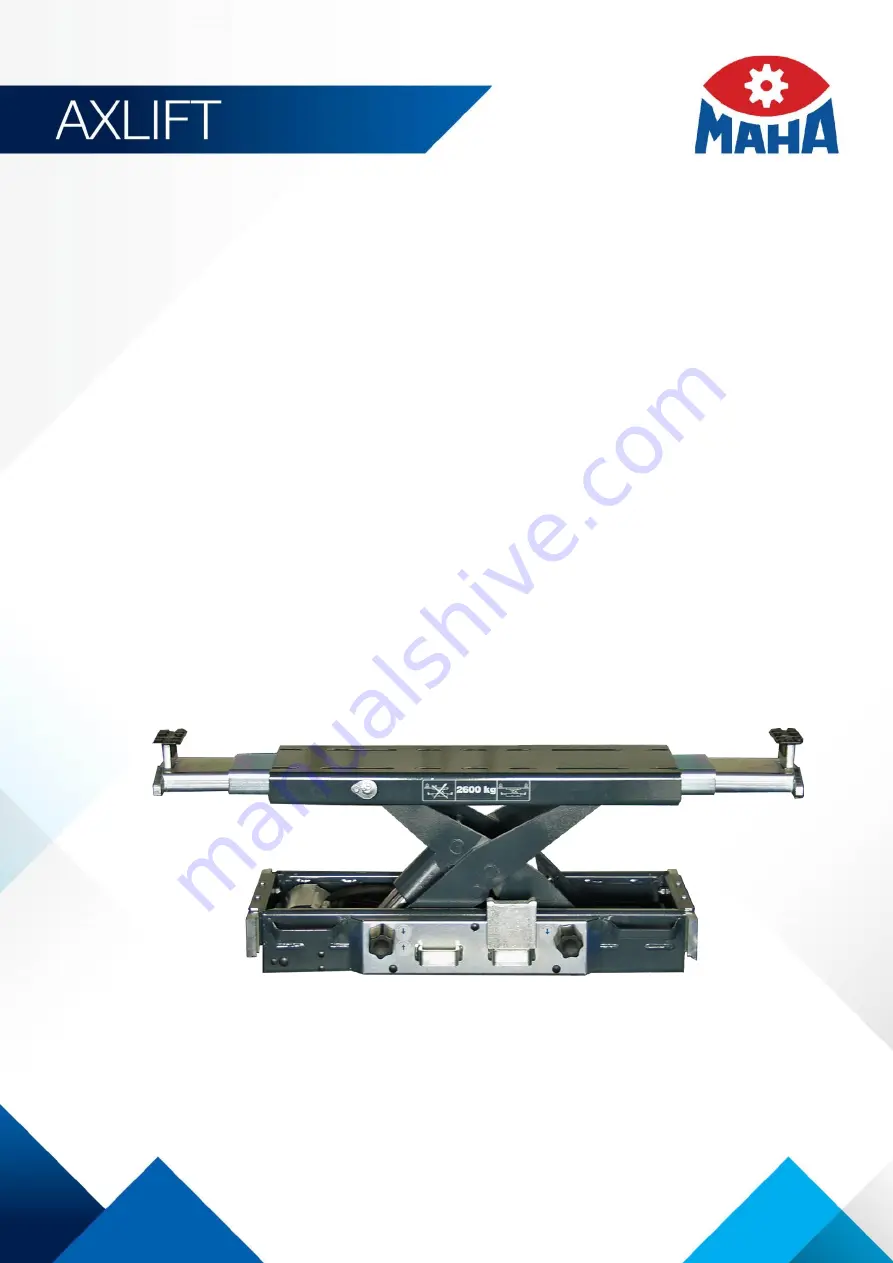
AL II
Axle Jack
Original Operating Instructions
BA082201-en
AL II 2.0
AL II 2.0 PH
AL II 2.6
AL II 2.6 PH
AL II 2.6 PH W
AL II 2.6 PH S
AL II 4.0 PH W


