background image

WE3107 v.110413

SAVE THIS MANUAL

You will need this manual for safety instructions, operating procedures, and warranty.  

Put it and the original sales invoice in a safe, dry place for future reference.

CONSERVEZ CE GUIDE

Vous aurez besoin de ce guide pour les instructions de sécurité, les procédures d’utilisation et la garantie. 

Conservez-le dans un endroit sûr et sec pour référence future. 

QUESTIONS?  1-800-567-8979


Model:


Our Customer Service staff are ready to provide assistance. 

If a part is damaged or missing, replacement parts can be 

shipped from our facility.

For help with assembly, or for additional product 

information, call our North American toll-free number:  

1-800-567-8979


Notre personnel de service à la clientèle sera prêt à 

fournir assistance. Si une pièce est endommagée ou 

manquante, des remplacements seront expédiés de notre 

usine.
Pour de l’aide avec l’assemblage, ou pour des 

informations additionnelles sur le produit, appeller notre 

numéro sans frais nord-américain : 1-800-567-8979
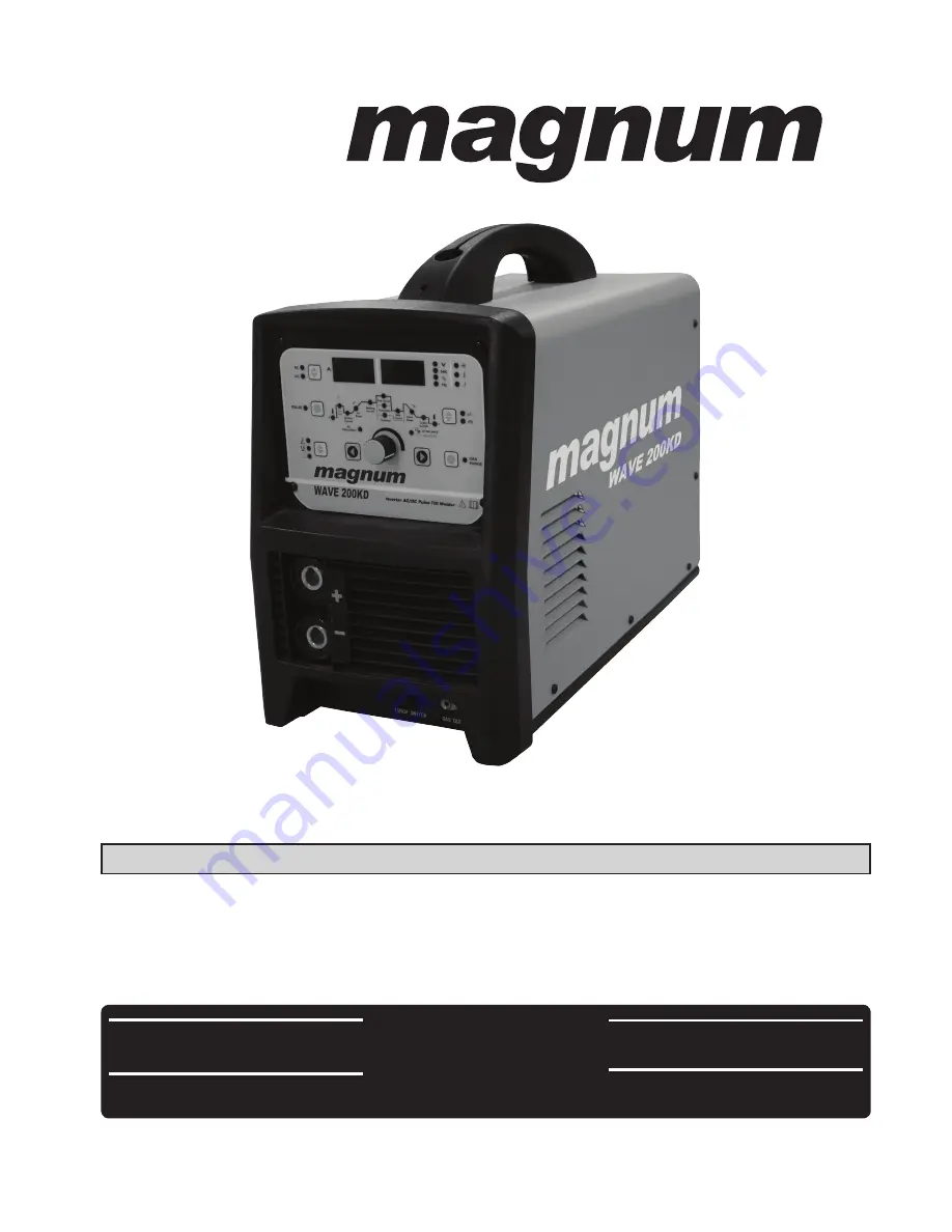
 

WAVE 200KD

AC/DC Pulse TIG/ARC Welder

Summary of Contents for WAVE 200KD

Page 1: ...del Our Customer Service staff are ready to provide assistance If a part is damaged or missing replacement parts can be shipped from our facility For help with assembly or for additional product information call our North American toll free number 1 800 567 8979 Notre personnel de service à la clientèle sera prêt à fournir assistance Si une pièce est endommagée ou manquante des remplacements seron...

Page 2: ...2 CATALOGUE GENERAL SAFETY RULES TECHNICAL SPECIFICATION KNOW YOUR WELDER INSTALLATION OPERATION TROUBLESHOOTING DIAGRAM PARTS LIST WARRANTY ...

Page 3: ... Always be aware of your work environment Be sure to keep other people especially children away from you while welding Keep harmful arc rays shielded from the view of others Mount the welder on a secure bench or cart that will keep the welder secure and prevent it from tipping over or falling 1 2 Your Welder s Condition Check ground cable power cord and welding cable to be sure the insulation is n...

Page 4: ...s Always attach ground clamp to the work piece or work table as close to the weld area as possible Do not touch the welding wire and the ground or grounded work piece at the same time Do not use a welder to thaw frozen pipes Fumes and Gases Fumes emitted from the welding process displace clean air and can result in injury or death Do not breathe in fumes emitted by the welding process Make sure yo...

Page 5: ...ts that are oil free with no pockets or cuffs that will collect sparks Do not have on your person any items that are combustible such as lighters or matches Keep work lead connected as close to the weld area as possible to prevent any unknown unintended paths of electrical current from causing electrical shock and fire hazards To prevent any unintended arcs cut wire back to stick out after welding...

Page 6: ...ken parts will affect the WAVE 200KD operation Replace or repair damaged or worn parts immediately Store idle WAVE 200KD When WAVE 200KD is not in use store it in a secure place out of the reach of children Inspect it for good working condition prior to storage and before re use Notice If the welder continues to work too long time the Protection Indicator on the panel would be on indicating that t...

Page 7: ... A 10 200 Stick Welding Current A 5 170 Current Up Time S 0 15 Current Drop Time S 0 25 Pulse Frequency Hz 0 5 250 Pulse Width Adjustment DC 15 85 Clear Area Control AC 15 65 Gas Stop Delay Time S 0 30 Rated Duty Cycle 35 Cooling Type Air cooling Effiency η 85 Power Factor Cosφ 0 92 Insulation Degree H Cover Protection Degree IP IP21S Weight kg 19 5 Dimension L W H mm 500 240 410 No special advice...

Page 8: ...2 4 90 180 10 12 3 4 AC Pure Aluminium Alu Mag Alloy X groove 8 12 4 5 150 220 Positive 12 16 4 5 90 1 50 KNOW YOUR WELDER Description WAVE200KD is a digitization model can be used for MMA ACTIG DCTIG and PULSE TIG the parameters can be preset and showed welding current and voltage can real time display this is very easy operation 1 Front panel 1 1 Know the Front panel 1 2 Current display To show ...

Page 9: ...Press this knob again the indicator extinguish gas check function does not work 1 9 Voltage display To show the preset current when setting and the welding current when working 1 10 Procedure parameter display This part is to show the procedure when the indicator lights the corresponding parameter can be adjusted with the adjustment knob See following details 1 Pre flow Time indicator light 8 Puls...

Page 10: ...shock Do not remove grounding prong or alter the plug in any way Do not use any adapters between the welder s power cord and the power source receptacle Make sure the POWER switch is OFF when connecting your welder s power cord to a properly grounded 220 VAC 60 HZ Single Phase 50 Amp input power supply 2 EXTENSION CORD We do not recommend an extension cord because of the voltage drop they produce ...

Page 11: ...om electrical shock If you are not sure if your outlet is properly grounded have it checked by a qualified electrician Do not cut off the grounding prong or alter the plug in any way and do not use any adapter between the welder s power cord and the power source receptacle Make sure the POWER switch is OFF then connect your welder s power cord to a properly grounded 220 VAC 60 HZ single phase 50 a...

Page 12: ...ch set on different gears to choose the welding method 2 step four step See the details introduction is Technical Instruction Step1 Press this knob choose MMA the current display shows the pre set current voltage display shows the open circuit voltage Step2 Press this knob to choose the parameter Step3 Use this adjustment to adjust the parameter selected on Step2 Step3 Use this adjustment to adjus...

Page 13: ...nt to adjust the stopping gas delay time 2 3 Trigger Mode Control Button HF TIG and LIFT TIG Mode only The trigger mode control is used to switch the functionality of the torch trigger between 2T normal and 4T latch mode 2 3 1 2T Normal Mode In this mode the torch trigger must remain depressed for the welding output to be active Press and hold the torch trigger to activate the power source weld Re...

Page 14: ...NOTE This Up Slope operates in 4T TIG modes only and is used to set the time for the weld current to ramp up after the torch trigger switch has been pressed then released from Initial Current to High or BASE current 2 4 AC TIG welding Set Welding mode knob to TIG and AC DC transfer knob to AC would enter into AC TIG welding mode Then to choose by Parameter knob Parameter positive knob to adjust th...

Page 15: ... the TIG torch contact the workpiece press the switch at this time there will be a 50A arc starting current press the switch more than 0 5s Pre flow time not included then lift the torch make the distance between the torch and workpiece is 2 4mm then start the welding 3 Stick welding skill 3 1 Welding positions There are two basic positions for welding Flat and Horizontal Flat welding is generally...

Page 16: ...on A poor connection at the ground clamp will waste power and heat Make sure the ground clamp touches the metal 3 4 ELECTRODE The welding electrode is a rod coated with a layer of flux When welding electrical current flows between the electrode rod and the grounded metal work piece The intense heat of the arc between the rod and the grounded metal melts the electrode and the flux For best performa...

Page 17: ... c The bead will be flat and porous 3 5 3 d Rod may be freeze or stick to work piece Note Rate of travel over the work also affects the weld To ensure proper penetration and enough deposit of rod the arc must be moved slowly and evenly along the weld seam 3 6 SETTING THE AMPERAGE CONTROL The welder has an infinite current control It is capable of welding with electrodes up to 3 32 diameter There i...

Page 18: ...rt arc and then raise it quickly about 1 8 inch gap between the rod and the work piece see following picture It is important that the gap be maintained during the welding process and it should be neither too wide or too narrow If too narrow the rod will stick to the work piece If too wide the arc will be extinguished It needs much practice to maintain the gap The beginners may usually get sticker ...

Page 19: ...ll allowing slow enough travel speed to achieve good penetration A good starting point for your electrode angle is about 30 degrees DOWN from being perpendicular to the work piece 3 7 5 Judge the good weld bead When the trick of establishing and holding an arc has been learned the next step is learning how to run a good bead The first attempts in practice will probably fall short of acceptable wel...

Page 20: ...s and protect the hands and other exposed parts of the body with protective garments or if possible work with a shield between the body and the work piece The intense heat produced at the arc sets up strains in the metal joined by welding Peening the weld not only removes the scale left behind in the welding but relieves the internal strains developed by the heating and cooling process 4 TIG weldi...

Page 21: ...21 Tungsten Electrode Current Ranges Guide for Selecting Filler Wire Diameter Tungsten Electrode Types Aluminium Welding Material ...

Page 22: ...nd the disconnected wire and Connect reliably Torch switch broken Replace the torch Main PC board broken Replace the PC board Run on plate Replace the run on plate 2 No piloting high frequency Cable broken fallen off Find the disconnected wire and Connect reliably No Argon input Check the flow meter and resume supplying gas to the welder Main PC board broken Replace the PC board Electromagnetism V...

Page 23: ...en fallen off Find the disconnected wire and Connect reliably 6 No display on the AMP meter Main PC board broken Replace the PC board Wrong connection between torch and welder Check and correct according the manual Argon not pure Use 99 99 pure Argon 7 Arc piloting not smooth Tungsten electrode or pin broken Use qualified Tungsten electrode 8 Power trip First turning on after power long time 2days...

Page 24: ...30 Remote control absorption module 1 4 1 1 05 11 0062 Secondary inverter arc plate 1 5 2 05 17 028 Tension disc 2 6 2 04 30 103 Cable holder 1 7 1 1 11 34 0046 Power line 1 8 2 07 80 987 Switch 1 9 2 07 54 115 Aerial socket 1 10 1 1 01 03 1740 Back panel 1 2 02 02 034 Connecting screw rod 1 11 2 06 14 813 Copper nut 1 ...

Page 25: ... 2 03 30 1302 Gun switch wiring harness 1 27 2 05 05 140 Plastic panel 1 28 1 2 08 04 0171 Torch 1 29 1 2 08 02 0466 Earth cable 1 30 2 07 57 960 Europe type quick socket 2 31 2 07 11 022 Potentiometer knob 1 32 1 1 02 01 9020 Board support plate 1 33 1 1 05 07 0157 Faceplate 1 34 1 1 11 34 0043 Hall 1 35 2 07 43 963 Secondary rectifier heat sink down 1 36 2 07 28 813 Fast recovery diode 2 37 2 07...

Reviews: