background image

P.N.56622

.B

_EN


10/2020

‐‐ 

ORIGINAL


INSTRUCTIONS

 ‐‐


Drafted in accordance with the essential requirement of health and safety 1.7.4 of Annex I to Directive 2006/42 / EC


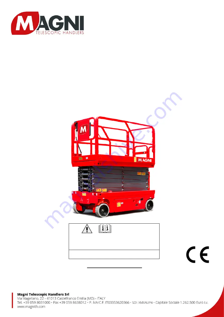
SELF-PROPELLED SCISSOR LIFTS 

OPERATOR’S MANUAL 

with Maintenance Information


(For ES0808H / ES1008H / ES0812H / ES1012H / ES1212H / ES1412H / ES1612HLB / ES1612HCP) 

(For ES0808E / ES1008E / ES0812E / ES1012E / ES1212E / ES1412E / ES1612ELB / ES1612ECP) 

( Hydraulic Motor / DC Motor Drive ) 

  WARNING 

THE MANIFACTURER SHALL NOT BE HELD LIABLE IN CASE OF 

FAULTS OR ACCIDENTS DUE TO NEGLIGENCE, INCAPACITY, 

INSTALLATION BY UNQUALIFIED TECHNICIANS AND IMPROPER USE 

OF THE MACHINE. 

DO NOT OPERATE THIS MACHINE UNTIL YOU READ AND 

UNDERSTAND ALL THE DANGERS, WARNINGS AND CAUTIONS IN 

THIS MANUAL. 


Summary of Contents for ES0808E

Page 1: ...08H ES0812H ES1012H ES1212H ES1412H ES1612HLB ES1612HCP For ES0808E ES1008E ES0812E ES1012E ES1212E ES1412E ES1612ELB ES1612ECP Hydraulic Motor DC Motor Drive WARNING THE MANIFACTURER SHALL NOT BE HEL...

Page 2: ...i Version of the Record Version Number Create Date SM0110111MN_Rev1 0 2017 04 SM0110111MN_Rev2 0 2017 11 SM0110111MN_Rev3 0 2018 01 SM0110111MN_Rev4 0 2018 07 SM0110111MN_Rev4 1 2019 10 SM0110111MN_R...

Page 3: ......

Page 4: ...ort and Lifting Instructions 57 Storage 61 Maintenance 62 Schematic 91 Inspection and Repair Log 101 Owners Users and operators We appreciate your choice of our machine for your application Our number...

Page 5: ...2 41013 Castelfranco Emilia Modena Italia Tel 39 059 8630811 Fax 39 059 8638012 Web www magnith com E mail commerciale magnith com MAKER Zhejiang Dingli Machinery Co Ltd 1255 Baiyun South Road Leidian...

Page 6: ...understand and obey all applicable governmental regulations You are properly trained to safely operate the machine Decal Legend DINGLI product decals use symbols color coding and signal words to ident...

Page 7: ...Allow for platform movement electrical line sway or sag and beware of strong or gusty winds Keep away from the machine if it contacts energized power lines Personnel on the ground or in the platform...

Page 8: ...ion deck allowable maximum load 113kg Maximum capacity ES0812E Maximum occupants Indoor Outdoor use 2 Platform allowable maximum load 540kg Extension deck allowable maximum load 113kg Maximum capacity...

Page 9: ...rom normal motion by an adjacent structure All personnel must be removed from the platform before attempting to free the platform using the ground controls Use extreme care and slow speeds while drivi...

Page 10: ...ES1612HLB ELB ES1612HCP ECP Do not modify or alter an aerial work platform without prior written permission from the manufacturer Mounting attachments for holding tools or other materials onto the pla...

Page 11: ...a lanyard attached to an authorized lanyard anchorage point Attach only one 1 lanyard per lanyard anchorage point Do not sit stand or climb on the platform guard rails Maintain a firm footing on the p...

Page 12: ...ous locations where potentially flammable or explosive gases or particles may be present Damaged Machine Hazard Do not use a damaged or malfunctioning machine Conduct a thorough pre operation inspecti...

Page 13: ...ct the battery charger to a grounded AC 3 wire electrical outlet only Inspect daily for damaged cords cables and wires Replace damaged items before operating Metallic parts of the battery cells are al...

Page 14: ...h this marking are recyclable goods and must be sent for recycling Used batteries which are not sent for recycling are to be disposed of as special waste under the relevant regulations Lockout after E...

Page 15: ...ge point 5 Platform guard rails 6 Platform extension release pedal 7 Main platform 8 Platform entry gate 9 Scissor arms 10 Lift cylinder 11 Ground controls on opposite side of machine 12 Entry ladder...

Page 16: ...1012E 34871 Decal Label Capacity 320kg 1 ES1212H ES1212E 34872 Decal Label Capacity 320kg 1 ES1412H ES1412E 51918 Decal Label Capacity 250kg 1 ES1612HLB ES1612ELB ES1612HCP ES1612ECP 7 34925 Decal Ins...

Page 17: ...l force 400N Indoor 200N Outdoor 2 ES0808H ES0808E ES1212H ES1212E 37507 Decal Symbols Max manual force 400N Indoor 2 ES1008H ES1008E ES1612HLB ES1612ELB ES1612HCP ES1612ECP 38250 Decal Symbols Max ma...

Page 18: ...2ELB 52143 Decal Cosmetic ES1612HCP 2 ES1612HCP 52145 Decal Cosmetic ES1612ECP 2 ES1612ECP 19 38437 Decal Symbols Do not alter or disable limit switch 1 20 34926 Decal Instructions Tie down point 4 21...

Page 19: ...OPERATOR S MANUAL with Maintenance Information Decals 14 Safety tape 1 2 3 4 5 1 1 1 6 7 20 21 9 12 13 16 17 18 8 15 7 20 21 8 17 18 16 15 19 22 23 15 20 21 20 21 8 8 10 11 24 11 13 2 11 14...

Page 20: ...OPERATOR S MANUAL with Maintenance Information Decals 15...

Page 21: ...OPERATOR S MANUAL with Maintenance Information Decals 16...

Page 22: ...ximum hydraulic pressure functions 240 bar System voltage 24 V Tire size 381 127 mm Airborne noise emissions 70 dB Maximum sound level at normal operating workstations A weighted Vibration value does...

Page 23: ...imum hydraulic pressure functions 240 bar System voltage 24 V Tire size 381 127 mm Airborne noise emissions 70 dB Maximum sound level at normal operating workstations A weighted Vibration value does n...

Page 24: ...aximum hydraulic pressure functions 240 bar System voltage 24 V Tire size 381 127 mm Airborne noise emissions 70 dB Maximum sound level at normal operating workstations A weighted Vibration value does...

Page 25: ...imum hydraulic pressure functions 240 bar System voltage 24 V Tire size 381 127 mm Airborne noise emissions 70 dB Maximum sound level at normal operating workstations A weighted Vibration value does n...

Page 26: ...ximum hydraulic pressure functions 240 bar System voltage 24 V Tire size 381 127 mm Airborne noise emissions 70 dB Maximum sound level at normal operating workstations A weighted Vibration value does...

Page 27: ...ximum hydraulic pressure functions 240 bar System voltage 24 V Tire size 381 127 mm Airborne noise emissions 70 dB Maximum sound level at normal operating workstations A weighted Vibration value does...

Page 28: ...Maximum hydraulic pressure functions 240 bar System voltage 24 V Tire size 381 127 mm Airborne noise emissions 70 dB Maximum sound level at normal operating workstations A weighted Vibration value do...

Page 29: ...Maximum hydraulic pressure functions 240 bar System voltage 24 V Tire size 381 127 mm Airborne noise emissions 70 dB Maximum sound level at normal operating workstations A weighted Vibration value do...

Page 30: ...imum hydraulic pressure functions 240 bar System voltage 24 V Tire size 381 127 mm Airborne noise emissions 70 dB Maximum sound level at normal operating workstations A weighted Vibration value does n...

Page 31: ...mum hydraulic pressure functions 240 bar System voltage 24 V Tire size 381 127 mm Airborne noise emissions 70 dB Maximum sound level at normal operating workstations A weighted Vibration value does no...

Page 32: ...aximum hydraulic pressure functions 240 bar System voltage 24 V Tire size 381 127 mm Airborne noise emissions 70 dB Maximum sound level at normal operating workstations A weighted Vibration value does...

Page 33: ...ximum hydraulic pressure functions 240 bar System voltage 24 V Tire size 381 127 mm Airborne noise emissions 70 dB Maximum sound level at normal operating workstations A weighted Vibration value does...

Page 34: ...ximum hydraulic pressure functions 240 bar System voltage 24 V Tire size 381 127 mm Airborne noise emissions 70 dB Maximum sound level at normal operating workstations A weighted Vibration value does...

Page 35: ...ximum hydraulic pressure functions 240 bar System voltage 24 V Tire size 381 127 mm Airborne noise emissions 70 dB Maximum sound level at normal operating workstations A weighted Vibration value does...

Page 36: ...Maximum hydraulic pressure functions 240 bar System voltage 24 V Tire size 381 127 mm Airborne noise emissions 70 dB Maximum sound level at normal operating workstations A weighted Vibration value doe...

Page 37: ...Maximum hydraulic pressure functions 240 bar System voltage 24 V Tire size 381 127 mm Airborne noise emissions 70 dB Maximum sound level at normal operating workstations A weighted Vibration value do...

Page 38: ...X 12 100 Quantity 4 Battery capacity maximum 100Ah Maintenance free Yes ES1212E ES1212H optional Voltage 6VDC Type T 125 Plus Quantity 4 Battery capacity maximum 240Ah Maintenance free No ES1412E ES14...

Page 39: ...nd controls will operate 2 Platform up down switch Move the switch up and the platform will raise Move the switch down and the platform will lower 3 Circuit breaker When the current was overloaded the...

Page 40: ...Platform Control Panel 1 Thumb rocker switch 2 Drive function select button 3 Drive speed button 4 Red Emergency Stop button 5 LED readout screen 6 Horn button 7 Lift function select button 8 Proport...

Page 41: ...vate the lift function 8 Proportional control handle Lift function Press and hold the function enable switch to enable the lift function on the platform control handle Move the control handle in the d...

Page 42: ...iscover if anything is apparently wrong with a machine before the operator performs the function tests The pre operation inspection also serves to determine if routine maintenance procedures are requi...

Page 43: ...anifolds Battery pack and connections Drive motors Wear pads Tires and wheels Ground strap Limit switches alarms and horn Nuts bolts and other fasteners Platform overload components Platform entry gat...

Page 44: ...if the workplace is suitable for safe machine operation It should be performed by the operator prior to moving the machine to the workplace It is the operator s responsibility to read and remember the...

Page 45: ...machine as it was intended Fundamentals The function tests are designed to discover any malfunctions before the machine is put into service The operator must follow the step by step instructions to te...

Page 46: ...s at 180 beeps per minute The alarm that goes off when the machine is not level sounds at 180 beeps per minute An optional automotive style horn is also available 10 Turn the key switch to off or plat...

Page 47: ...wn arrow Result The platform should lower The descent alarm should sound while the platform is lowering Test the Steering Note When performing the steer and drive function tests stand in the platform...

Page 48: ...form 42 Place a 3 5 20cm or similar piece of wood under both wheels on one side and drive the machine up onto them 43 Raise the platform approximately 2m from the ground Result The platform should sto...

Page 49: ...ndle 54 Move the control handle in the direction indicated by the blue up arrow and then move the control handle in the direction indicated by the yellow down arrow Result The drive function should no...

Page 50: ...used to perform some relatively straightforward calculations on subsystem to determine the overall PL of the system Reliability data diagnostic coverage DC the system architecture Category common cau...

Page 51: ...unction enable switch on the control handle 3 Move the control handle according to the markings on the control panel To Steer 1 Press the drive function select button 2 Press and hold the function ena...

Page 52: ...of wood run and multiply by 100 Example Run 3 6 m Rise 0 3 m 0 3 m 3 6 m 0 083 x 100 8 3 If the slope exceeds the maximum slope or side slope rating the machine must be winched or transported up or do...

Page 53: ...form right rail assembly Keep hands clear of pinch points 8 Carefully open the gate and move to the rear step or the ground 9 From the rear step or from the ground remove the left rear main deck wire...

Page 54: ...All Motion 35 Pressure Sensor 2 Fault Disables All Motion 36 Low Battery Alert Warning Only 42 Platform Left Turn Switch ON at power up Message Warning Only 43 Platform Right Turn Switch ON at power...

Page 55: ...roller Dependent 76 Motor Controller Left Drive Motor Fault Controller Dependent 77 Motor Controller Right Drive Motor Fault Controller Dependent 78 Pump Motor Short Fault Disable Lifting and Driving...

Page 56: ...nd then the sensor itself Also check to make sure that the correct option is properly selected or not for load sensing 36 Low Voltage Alert Check battery voltage and charge batteries if necessary 42 P...

Page 57: ...the Motor Controller 63 Motor Controller Motor Output fault Check wiring first then cycle power If needed replace controller 64 Motor Controller SRO Fault Look at motor enable delay with the Dingli Sc...

Page 58: ...resolve the issue replace the Motor Controller 78 Pump Motor Short Fault Check connections to the pump motor Cycle power to the lift and if that does not resolve the issue replace the Motor Controller...

Page 59: ...ght Motor Field Short Check connections of the field wires or leakage to the vehicle frame 99 Over 99 Load Warning Platform has reached its limit of weight Do not add more load OL Overloaded Platform...

Page 60: ...ry 1 Be sure the batteries are connected before charging 2 Open the battery compartment The compartment should remain open for the entire charging cycle Maintenance free battery 3 Connect the battery...

Page 61: ...e Do not overfill Note In order to achieve an optimal service life discharge of over 60 of the rated capacity should be avoided Discharge of over 80 of the rated capacity is a deep discharge and is no...

Page 62: ...transport vehicle bed exceeds the maximum slope rating the machine must be loaded and unloaded using a winch as described Brake Release Operation For the Hydraulic Motor Drive Model 1 Chock the wheel...

Page 63: ...the extension deck s Turn the key switch to the off position and remove the key before transporting Inspect the entire machine for loose or unsecured items Use the tie down points on the chassis for...

Page 64: ...e with a Forklift Be sure the extension deck controls and component trays are secure Remove all loose items on the machine Fully lower the platform The platform must remain lowered during all loading...

Page 65: ...re on this page Attach the rigging only to the designated lifting points on the machine There are two lifting points on each end of the machine Adjust the rigging to prevent damage to the machine and...

Page 66: ...power switch key switch and emergency stop switch fully charge In order to ensure that these batteries stay ready for operation the following charging procedures must be applied The machine or check...

Page 67: ...h type of scheduled inspection Make copies of the Pre delivery Preparation report to use for each inspection Store completed forms as required Maintenance Schedule There are five types of maintenance...

Page 68: ...all be performed by qualified service technicians according to the manufacturer s specifications and the requirements listed in this manual Instructions Use the operator s manual on your machine The P...

Page 69: ...tag and remove the machine from service repair and re inspect it After repair place a check in the R box Legend Y yes acceptable N no remove from service R repaired Checklist A Y N R A 1 Inspect the m...

Page 70: ...that the operator s manual is present and complete in the storage container on the platform 2 Examine the pages of manual to be sure that they are legible and in good condition Result The operator s...

Page 71: ...A 3 Check the Batteries Proper battery condition is essential to good machine performance and operational safety Improper fluid levels or damaged cables and connections can result in component damage...

Page 72: ...the following table Model Scale line L ES0808H E ES1008H E ES0812H E ES1012H E 15 ES1212H E ES1412H E 17 5 ES1612HLB ELB ES1612HCP ECP 19 2 Add oil if necessary Do not overfill Original Hydraulic oil...

Page 73: ...is a one time procedure to be performed after the first 30 days or 40 hours of usage After this interval refer to the maintenance tables for continued scheduled maintenance Perform the following maint...

Page 74: ...and cable connections are tight 5 Fully charge the batteries Allow the batteries to rest 24 hours before performing this procedure to allow the battery cells to equalize Models without maintenance fr...

Page 75: ...ed a 6V batteries b power switch c fuse d battery charger a 12V batteries b power switch c fuse d battery charger All models 13 Check each battery pack and verify that the batteries are wired correctl...

Page 76: ...Failure to find and replace burnt chafed corroded or pinched wires could result in unsafe operating conditions and may cause component damage Electrocution burn hazard Contact with electrically charg...

Page 77: ...Inspect the Tires and Wheels including castle nut torque DINGLI requires that this procedure be performed every 250 hours or quarterly whichever comes first Maintaining the tires and wheels in good c...

Page 78: ...osition Result No machine functions should operate Note The red Emergency Stop button at the ground controls will stop all machine operation even if the key switch is switched to platform control B 5...

Page 79: ...erformed every 250 hours or quarterly whichever comes first Proper brake action is essential to safe machine operation The drive brake function should operate smoothly free of hesitation jerking and u...

Page 80: ...Position DINGLI requires that this procedure be performed every 250 hours or quarterly whichever comes first Proper drive functions are essential to safe machine operation The drive function should r...

Page 81: ...ive function should respond quickly and smoothly to operator control Drive performance should also be free of hesitation jerking and unusual noise over the entire proportionally controlled speed range...

Page 82: ...e function should respond quickly and smoothly to operator control Drive performance should also be free of hesitation jerking and unusual noise over the entire proportionally controlled speed range P...

Page 83: ...raulic oil is essential for good machine performance and service life Dirty oil may cause the machine to perform poorly and continued use may cause component damage Extremely dirty conditions may requ...

Page 84: ...eed to step 3 Note When checking for positive tank cap venting air should pass freely through the cap 3 Using a mild solvent carefully wash the cap venting system Dry using low pressure compressed air...

Page 85: ...ds clear of the safety arm when lowering the platform 6 Turn the key switch to the off position 7 Tag and disconnect the platform control box at the platform 8 Follow the platform control cable down t...

Page 86: ...hen lowering the platform 21 Turn the key switch to the off position 22 Disconnect the platform controls from the ECU cable 23 Securely install the connector of the ECU cable into the platform control...

Page 87: ...e guard contacts the block and does not fully deploy the LED readout screen does not show code 18 the alarm does not sound and the machine will continue to lift the platform after the pothole guards a...

Page 88: ...r arm and rotate up to a vertical position 3 Lift the upper safety arm move it to the center of the scissor arm and rotate down to a vertical position for ES1412H E ES1612HLB ELB ES1612HCP ECP 4 Lower...

Page 89: ...ch is adjustable and located at the barrel end of the lift cylinder is used to determine when the hydraulic lift cylinder requires too much pressure to support the load inside the platform When this o...

Page 90: ...e the platform Release the toggle switch Result The alarm should not sound The system is functioning correctly Result The alarm sounds The system is not functioning correctly Troubleshoot the limit sw...

Page 91: ...lic tank is a vented type tank The breather cap has an internal air filter that can become clogged or over time can deteriorate If the breather cap is faulty or improperly installed impurities can ent...

Page 92: ...ure the distance between the number one arm cross tube and the chassis deck at the ground controls side of the non steer end of the machine Result The measurement is 34mm or more Proceed to step 2 Res...

Page 93: ...th hot oil may cause severe burns The hydraulic tank return filter is mounted on the bracket between the function manifold and the hydraulic power unit 1 Clean the area around the oil filter Remove th...

Page 94: ...2 Open the power unit module tray 3 Remove the oil drain plug at bottom 4 Drain all of the oil into a suitable container 5 Tag and disconnect the hydraulic tank return line from the hydraulic filter...

Page 95: ...ting onto the hydraulic filter head and torque 15 Fill the tank with hydraulic oil until the fluid is full in the hydraulic tank Do not overfill 16 Activate the pump to fill the hydraulic system with...

Page 96: ...2 P M T BRK RV1 SV1 FR RV4 CV2 RV3 CV1 1 1mm SV4 SV3 D3 D2 D1 D4 L P41 P42 CV2 1 5mm Lower valve NBCY 1001A 11 235bar 3 45bar Tank Pump 5802 4 12 Valve 5805 0116R Hand pump 5805 0412 960020A10 Platfor...

Page 97: ...B 11 120bar 235bar 3 45bar RV2 150bar ES1212H RV2 190bar ES1412H 180bar Pump 5802 4 12 Valve 5805 0116R Tank Platform loading Option Steer cylinder Lift cylinder Upper lift cylinder Hand pump 5805 041...

Page 98: ...SV1 FR RV4 CV2 RV3 CV1 1 1mm SV4 SV3 D3 D2 D1 D4 L P41 P42 RV5 CV2 0 6mm 1 0mm Lower valve NBCY 1001A 11 Lower valve NBCY 1001B 11 120bar 235bar 3 45bar Pump 5802 4 12 Valve 5805 0116R Tank Platform...

Page 99: ...08E ES0812E ES1012E Lift cylinder Platform loading Option Steer cylinder P M SV2 FRRV1 SV1 S1 S2 L T Tank Pump 5802 3 2 14 Function valve DPH 0918 10 1mm 1mm 1 5mm Lower valve NBCY 1001A 11 120bar RV1...

Page 100: ...1412E Lower valve NBCY 1001A 11 Lower valve NBCY 1001B 11 RV1 150bar ES1212E RV1 190bar ES1412E Platform loading Option Steer cylinder Lift cylinder Upper lift cylinder Tank Pump 5802 4 12 Function va...

Page 101: ...ES1612ELB ES1612ECP Platform loading Option Steer cylinder Lift cylinder Upper lift cylinder Tank Pump 5802 4 12 Function valve DPH 0918 10 1mm 1mm 1 0mm 0 6mm 120bar Lower valve NBCY 1001A 11 Lower...

Page 102: ...SQ4 010A 1 RD 20 010A 11 RD 18 RD 22 RD 22 B 3 BK 18 B 2 BK 20 GND 1 BK 18 GND BK 18 010A 14 RD 20 9B WH 18 12C WH 20 11B WH 20 10B WH 20 12B WH 20 12A WH 20 11C WH 20 4B WH 20 11A WH 20 3C WH 20 6B...

Page 103: ...ND 6 BK 18 B BK 14 B1 YV7 YV5 YV6 YV1 YV3 YV4 8A 2 WH 20 8A 3 WH 18 JS1 SB4 S2 SB5 SB6 SB7 SB8 B3 CAN_H CAN_L SB3 PCU 2 1 B2 1 2 3 TILT AS1 LS1 YV2 HL2 YV8 BK 2 BK 2 RD 2 HM B J1 J3 M B 2 1 MC1 M1 GND...

Page 104: ...10 BK 18 CONTROL RD 18 CONTROL WH 18 KM1 GND 11 BK 16 GND 1 BK 16 RD 2 8A WH 20 10B WH 20 B B RD 16 EXCITATION WH 16 BK 2 BK 8 BU 11 BK 8 BU 11 RD 8 BU 11 RD 8 BU 11 M1 M2 M3 RD 2 RD 16 BK 16 BK 16 RD...

Page 105: ...6 RD 18 SB2 010 1 RD 18 010A WH 20 010A 2 RD 18 010A 4 RD 20 010A 5 RD 20 010A 10 RD 20 SQ4 B 1 WH 20 SQ3 5A 2 RD 18 010A 2 RD 18 010A 3 RD 18 010A 4 RD 18 010A 5 RD 18 B A RD 18 B F A B C D 010 1 RD...

Page 106: ...OPERATOR S MANUAL with Maintenance Information Inspection and Repair Log 101 Inspection and Repair Log Date Comments...

Reviews: