


- 1 -
Select this connection when you want to view
or record a scrambled channel. With this con-
nection, channels cannot be changed on the
unit. You can view or record ONLY the chan-
nels you have selected on the cable box or
the satellite box.
• While you are recording, only the recorded
channel can be viewed.
To select channels of the cable box or
satellite box
1) Turn on the unit by pressing
[STANDBY-
ON]
, then press
[VCR/TV]
. The “POWER”
and the “VCR/TV” indicator on the front
panel will appear, then press
[CHANNEL
]
to select channel 3 or 4 (the same
channel as the output channel of the cable
box or satellite box).
• If you use the channel 4, you need to
change the unit’s RF output to channel 4.
Refer to “RF Output Channel”.
2) At the TV, select channel 3 or 4 (the same
channel as you have selected at step 1)).
3) On the cable box or satellite box, select the
channel you want to view or record.
If channel 3 is already occupied for broadcasting,
1) Set your TV to channel 4.
2) Insert a pre-recorded tape into this unit.
3) Press
[PLAY
B
B
]
once.
4) After a few seconds, hold
[PLAY
B
B
] on the unit
for 3 seconds.
• The RF output channel will change to channel 4 from channel 3 and you
will see a playback picture.
• When a picture does not appear on the TV screen, repeat step 4).
5) Press
[STOP
C
C
]
to stop playback.
You can use the AUDIO OUT jacks and
VIDEO OUT jack on the back of the
VCR if your TV has Audio/Video Input
jacks. In this case, you need to set the
TV to external Line Input Mode. Please
refer to your TV’s owner’s manual.
Owner’s Manual
Video Cassette Recorder
MSC455
1VMN21186 / HJ440CD
★★★★★
Printed in China
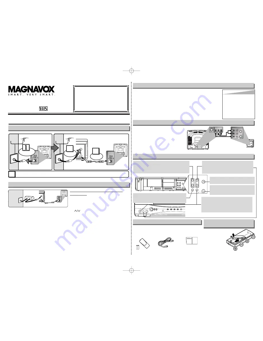
ANT
AUDIO
VIDEO
IN
OUT
OUT
IN
OUT
L
R
IN
ANT
AUDIO
VIDEO
IN
OUT
OUT
IN
OUT
L
R
IN
AUDIO IN jacks
Connect the audio cables coming from the
audio output jacks of a camcorder, another
VCR or an audio source here.
VIDEO IN jack
Connect the video cable coming from the
video output jack of a camcorder, another
VCR or an audio-visual source (laser disc
player, video disc player, etc.) here.
ANT IN jack
Connect your antenna or cable box here.
ANT OUT jack
Connect the supplied RF cable to the
antenna input jack on your TV.
Front & Rear Terminals
Stereo TV Connection
ANT
IN
OUT
L
R
AUDIO OUT
VIDEO
OUT
L
R
AUDIO IN
VIDEO
IN
AUDIO
ANT
IN
OUT
VIDEO
OUT
L
R
IN
IN
OUT
Audio/Video Cables
(not supplied)
(Back of TV)
(Back of VCR)
• Remote control
(NA374UD) with
two AA batteries
• RF cable
(WPZ0901TM002)
• Owner’s manual
(1VMN21186)
Supplied Accessory
Installing the Batteries for
the Remote Control
Install two AA batteries
(supplied) matching the
polarity indicated on
the bottom of the
remote control.
Hint
Hint
• The RF output channel
may not change when you
adjust tracking during
playback. In this case,
stop the playback, and
start the playback again.
After that, hold
[PLAY
B
B
]
on the VCR for 3 seconds
again.
VIDEO OUT jack
Connect the video cable here through the video
input jack of a camcorder, another VCR or a TV.
RF Output Channel
L - AUDIO - R
VIDEO
STANDBY-ON
IR
POWER
VCR/TV
CST.IN
TIMER
RECORD
CHANNEL
1. Before Using Your VCR
ANT
IN
OUT
RF Cable (supplied)
(Back of VCR)
(Back of TV)
(Back of TV)
Plug the AC power cords of the VCR and TV into the AC outlets.
4
Disconnect
Antenna
or
2
Connect
3
Connect
Antenna
or
Cable TV
Signal
Cable TV
Signal
RF Cable
(not supplied)
RF Cable
(not supplied)
Basic TV Connection
Hint for Cable Box or Satellite Box
ANT
IN
OUT
RF cable
(supplied)
RF Cables
(not supplied)
(Back of VCR)
IN
OUT
E
(Back of TV)
Antenna or
Cable TV
signal
(Cable box or
Satellite box)
If you need additional operating assis-
tance after reading this owner’s manual
or to order replacement accessories,
please call
TOLL FREE : 1-800-605-8610
http://www.funai-corp.com
AUDIO OUT jacks
Connect the audio cables here through to the audio
input jacks of a camcorder, another VCR, a stereo
amplifier or an audio system.
HJ440CD_EN.QX33 05.7.5 9:59 AM Page 1


