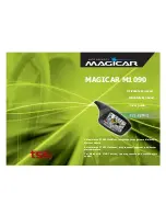
background image


DVP-120 Installation & Operating Instructions  


Summary of Contents for DVP-120

Page 1: ...DVP 120 Installation Operating Instructions...

Page 2: ...ystem Submenu 21 3 3 3 Configure Sensors Submenu 24 3 3 4 Configure Relays Horn Strobe Submenu 26 3 3 5 Configure Horn Submenu 27 3 3 6 Configure Strobe Submenu 28 3 3 7 Configure Zones Submenu 29 3 3...

Page 3: ...26 Figure 3 31 Turn On Delay 26 Figure 3 32 Minimum on time 26 Figure 3 33 Horn Summary 27 Figure 3 34 Horn Mode 27 Figure 3 35 Horn Turn On Delay 27 Figure 3 36 Horn Minimum on time 27 Figure 3 37 St...

Page 4: ...2 3 Connector to Sensor Channel Mapping 11 Table 2 4 Sensor Connectors Channel and Pin Assignments 11 Table 2 5 Relay Interface Signals and Connector Assignments 12 Table 2 6 Horn Strobe signals and...

Page 5: ...configured sensor In addition all control functions of the DVP 120 may be accessed through the system display and keypad 1 2 Features Twelve analog current loop input channels Three 16A 240 VAC SPDT...

Page 6: ...T SPECIFICATIONS Gas detection and exhaust fan control is provided by a Macurco DVP 120 system This System will use CM 2B or CM 3 Carbon Monoxide CO to current transducers ND 2 Nitrogen Dioxide to cur...

Page 7: ...Revision 0 07 7 Figure 1 2 DVP 120 Internal View...

Page 8: ...s below This warranty does not apply to units that have been altered or had repair attempted or that have been subjected to abuse accidental or otherwise The above warranty is in lieu of all other exp...

Page 9: ...ualified technicians should open the DVP 120 case and service the internal circuits Ensure power is removed from the DVP 120 prior to servicing the unit With the exception of the safety ground all fie...

Page 10: ...ctor into J4 on the PCB and ensure that it latches into the header properly Signal Terminal Connection Line 120 220 240 250 VAC J4 3 Neutral J4 1 Ground Ground Stud Table 2 1 Main Power Connections 2...

Page 11: ...r Pin Number CH 1 24 Vdc J7 5 CH 5 24 Vdc J13 5 CH 9 24 Vdc J11 5 CH 1 I loop J7 6 CH 5 I loop J13 6 CH 9 I loop J11 6 CH 1 I loop J7 7 CH 5 I loop J13 7 CH 9 I loop J11 7 CH 1 24Vdc Ret J7 8 CH 5 24V...

Page 12: ...the insulation of each wire back approximately 1 4 in 6 5 mm insert the bare wire into the terminal and tighten the screw clamp Ensure that the wire cannot easily be pulled from the connector Note tha...

Page 13: ...are wire into the terminal and tighten the screw clamp Ensure that the wire cannot easily be pulled from the connector When all wires are connected seat the modular connector into the PCB header ensur...

Page 14: ...e since a bridge rectifier is connected to the power input terminals All sensors used with the DVP 120 panel employ screw clamp terminal blocks for power and signal connections Polarity of the current...

Page 15: ...During the warm up period the keypad will be locked When the warm up period ends the LCD will start showing the normal display Figure 3 4 3 1 1 Status Light Display The POWER ALARM WARNING SILENCE REL...

Page 16: ...or down key is again used the display will switch back to the digit keys jumping to a particular sensor The MENU key has three functions First when the system is presenting the normal display pressing...

Page 17: ...her than prompting to show the relay If the sensor is indicating a gas level that is greater than the alarm or warning levels the gas reading will alternate with the words ALARM or WARNING as appropri...

Page 18: ...ble delay for the horn or strobe will sound see sections 3 3 5 3 and 3 3 6 3 When the HUSH key is pressed the internal buzzer will be silenced for fifteen 15 minutes If the horn or strobe turn on dela...

Page 19: ...ays and the external horn and strobe if desired When more than one zone is controlling a relay it only takes one zone to activate the relay but all controlling zones must release the relay before it w...

Page 20: ...ckground with the previously set configuration values In particular if an alarm condition is detected the alarm lamp the buzzer the horn and the strobe will operate as configured but the LCD will not...

Page 21: ...ample shows that the time is 22 55 10 55 PM The underlined characters indicate that the numeric keys can be used to set the current time of day When the first digit is entered and after the password i...

Page 22: ...in another The default configuration is Password 1234 Sensors Undefined Alarm levels CO 200 ppm HS 5 0ppm EX 4 000 ppm Alarm signals Buzzer Intermittent Horn Intermittent Strobe Continuous Warning si...

Page 23: ...hen the first digit is entered the panel will show P a s s w o r d _ _ _ 1 Figure 3 22 Password Prompt If the password is not entered correctly the panel will display W r o n g P a s s w o r d Figure...

Page 24: ...25 Sensor Type This display example shows that the sensor on channel 01 has been configured as a Carbon Monoxide sensor The valid entries for the sensor type are 1 Carbon Monoxide CO 2 Nitrogen Dioxi...

Page 25: ...000 ppm 5 LEL for methane Setting a warning level of 0 zero will disable warning detection for this particular sensor 3 3 3 5 Range S e n s o r 0 1 C O R a n g e _ 2 0 0 p p m Figure 3 28 Sensor s Ra...

Page 26: ...Off mode The relay modes are 1 ALARM 2 Normally Off default 3 Normally On Relay mode 1 is a special case This mode is only available on relay 1 and dedicates the relay to function as an alarm signal t...

Page 27: ...eys can be used to jump to a particular relay horn or strobe The relays are numbers 1 2 and 3 the horn is number 4 and the strobe is 5 3 3 5 2 Horn Mode H o r n N o r m O f f M o d e 2 Figure 3 34 Hor...

Page 28: ...can be used to jump to a particular relay horn or strobe The relays are numbers 1 2 and 3 the horn is number 4 and the strobe is 5 3 3 6 2 Strobe Mode S t r o b e N o r m O f f M o d e 2 Figure 3 38 S...

Page 29: ...by pressing the indicated digit key By default all three zones are configured not to control any devices When a new panel is first powered up this display will not show the digits only the underlined...

Page 30: ...2 0 4 1 1 Figure 3 46 Sensor Selection Sensors are included or removed from the group by entering the two digit channel number After a sensor is added or removed the list will be re sorted so it does...

Page 31: ...one outputs s are activated When the average is less than or equal to the falling trip point the zone output s are de activated If the average is between the two trip points the outputs remain in ther...

Page 32: ...ternal horn and the strobe 3 3 8 2 Alarm Buzzer Signal A l a r m S i g n a l s B u z z 2 I n t e r m i t Figure 3 53 Buzzer Alarm Signal This display example shows that the buzzer will signal an alarm...

Page 33: ...are signaled by the internal Buzzer only 3 3 8 6 Warning Buzzer Signal W a r n i n g S i g n a l s B u z z 5 O F F Figure 3 57 Buzzer Warning Signal This display example shows that the buzzer will not...

Page 34: ...rnal Buzzer only 3 3 8 10 Trouble Buzzer Signal T r o u b l e S i g n a l s B u z z 4 T r i p l e Figure 3 61 Buzzer Trouble Signal This display example shows that the buzzer will signal a trouble con...

Page 35: ...uble Signal This display example shows that the strobe will not signal a trouble condition The signal definitions are 1 Continuous 2 Intermittent one second on at two second intervals 3 Double Tap two...

Page 36: ...a trouble message on the digital display Macurco sensors may be tested by depressing the TEST button on the sensor printed circuit board or depending on the type of sensor the button on the interior...

Page 37: ...REPLACE THE SAFETY COVER on F3 before re applying power to the DVP 120 4 4 LCD Display unreadable It is possible that the LCD is unreadable due to temperature or aging of the control panel If this is...

Reviews: