BitVision Video Synthesizer
LZXINDUSTRIES.NET/BITVISION
OPERATING INSTRUCTIONS
BitVision
is a compact visual synthesizer designed for
audiovisualization. It creates a Composite Video output
signal which displays a 32x32 pixel image using the
currently selected 16-color palette.
Transformations can be applied to the current color palette
and horizontal/vertical display modes in realtime, creating
animation and movement. The manner in which the external
audio and the internal counter transform the image can be
changed via various modulation modes.
The goal of this project was to create a versatile video
generator with a vintage/imperfect response to color and
shape, such as what you might see when playing your Atari
2600 on an old CRT television in 1977. Colors will bleed
and slew due to the voltage-controlled color phase shifter,
giving a degree of chaotic analogue response and noise
missing when viewing simple pixel graphics on a modern
computer.
In addition to generating the video image, we packed in as
many modulation capabilities and controls as we could in
such a small package. In the tradition of the Atari Video
Music, an analogue envelope follower and frequency counter
track external audio signals and can modulate shape and
color via many variable modulation routings. We wanted an
audiovisualizer that could potentially provide live video for
an entire musical performance, so 16 separate preset
image/palette options are stored inside.
Finally, we wanted BitVision to be an expandable and
continually useful tool for creating video art. To this end
we’ve included an AVR-ISP programming header on the
circuit board which can be used to reprogram BitVision with
new images, palettes, or entirely alternate applications.
Adjust GAIN knob
Controls amplitude of the external audio signal and conse-
quently the sensitivity of the peak detector trigger. The LED
in between GAIN & DECAY knobs indicates peak detector.
Adjust DECAY knob
Controls the smoothness of the external audio signal’s
modulation.
Adjust PARAM#1 knob
Controls the frequency of the internal counter (indicated by
the LED between PARAM#1 & PARAM#2 knobs.) Rate is
adjustable between 1 frame (1/30th of a second) and 255
frames (8.5 seconds.)
Adjust PARAM#2 knob
Controls bias level for audio modulation modes. Tip: start
with PARAM#2 turned fully counter-clockwise, and adjust to
control overall intensity of the audio modulation as the song
builds.
Press PROGRAM button
Cycles current image and palette (16 sets).
Press MODE button
Cycles current audio modulation mode. 4 modes: off,
positive envelope, negative envelope, frequency-counter.
Press ACTION button
Cycles current peak detector action. 4 modes: off, horizon-
tal, vertical, horvertical.
Hold PROGRAM Press MODE button
Cycles current counter action. 13 modes: rotate palette,
shift hue (entire palette), shift value (entire palette), random
color (entire palette), random hue (entire palette), random
value (entire palette), invert hue (entire palette), shift hue
(random index), shift value (random index), random color
(random index), random hue (random index), random value
(random index), invert hue (random index).
Hold PROGRAM Press ACTION button
Cycles current display mode (all horizontal & vertical
combinations.)
Hold MODE Press PROGRAM button
Cycles current palette (without changing image)
WHAT’s NEXT?
Once you’ve become familiar with your new video synthe-
sizer, you may want to dig deeper into its’ functionality.
There is immense potential for reprogramming the BitVision
hardware for many exciting video generation applications, or
loading in your own images and palettes to the current
program. Stay tuned to
www.lzxindustries.net/bitvision
for more information on tools and resources.
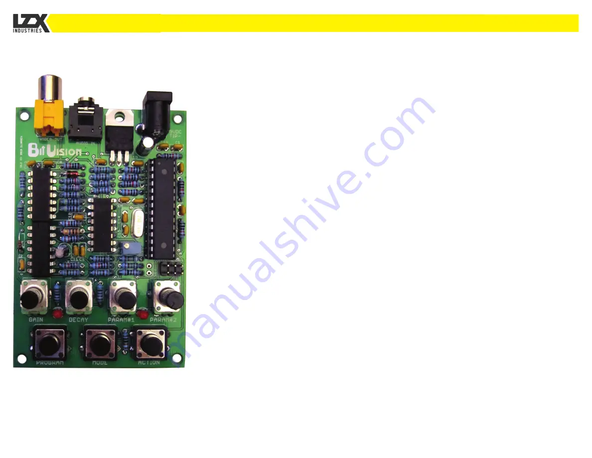
In order to use the BitVision you will need a standard
wall-wart adapter providing 9VDC power (Negative
Center/Tip) and at least 100mA. Connect the wallwart to the
DC input jack and the other end to the wall.
Connect your audio source (such as a stereo or instrument)
to the Audio In jack using a standard 3.5mm (1/8”) cable.
An 1/8” adapter or adapter cable can be used for sources
with only RCA or 1/4” jack outputs.
Connect the Video Out jack on the BitVision circuit board to
a Composite Video input jack on your television or other
video device.
You should now be seeing video output from the Bitvision.
If you just built your BitVision from a kit, adjust TR1 trimmer
with a small flathead screwdriver for desired color range.
For suggestions on where to buy cables or a wall-wart
power adapter, visit
www.lzxindustries.net/bitvision.
SETUP
OPERATION & ASSEMBLY MANUAL
INTRODUCTION
VERSION 1.2