luxvision SL 880, User Manual
The luxvision SL 880 user manual is an essential tool for maximizing your product experience. This comprehensive manual provides step-by-step instructions and valuable insights to optimize the performance of your luxury vision device. Download the manual for free at manualshive.com to unlock the full potential of your SL 880.
Share
Download


Reviews:
No comments
Related manuals for SL 880

Stemi DV4
Brand: Zeiss Pages: 38

LCDStar 200x-800x LED
Brand: Omegon Pages: 2

MEC4
Brand: Unitron Pages: 20

RV30A-DH
Brand: LW Scientific Pages: 1

100 series
Brand: Technic Pages: 24
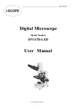
DN117D-LED
Brand: I-Scope Pages: 19

M82ES Series
Brand: Omax Pages: 13

DELio 601 871
Brand: Jeulin Pages: 32

BX61
Brand: Olympus Pages: 40

SV601
Brand: SVBONY Pages: 24

SV603
Brand: SVBONY Pages: 28

SM402
Brand: SVBONY Pages: 29

SV605
Brand: SVBONY Pages: 33

SV604
Brand: SVBONY Pages: 50

SV606
Brand: SVBONY Pages: 81

PKL
Brand: Meiji Techno Pages: 15

MT-30 Series
Brand: Meiji Techno Pages: 12

ML 8500 Series
Brand: Meiji Techno Pages: 11


