LS tractor MT5 Series, Operator'S Manual
The LS Tractor MT5 Series Operator's Manual is a comprehensive guide for users, providing detailed instructions on operating and maintaining their tractor. Customers can easily download this manual for free from our website, ensuring they have access to essential information whenever they need it.
Share
Download


Reviews:
No comments
Related manuals for MT5 Series
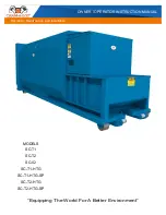
SC-02
Brand: CRAM-A-LOT Pages: 42

32
Brand: GOLDONI Pages: 43

IN 900 BIC UK
Brand: Amica Pages: 16

490-900-0024
Brand: MTD Pages: 16

TG Series
Brand: New Holland Pages: 36

GKN HOLHS
Brand: WALTERSCHEID Pages: 20

MTT 2012 Series
Brand: Eagle Tugs Pages: 214

Proxima Plus Series
Brand: Zetor Pages: 254

New Leader NL4330G4
Brand: FENDT Pages: 21

380-152A
Brand: Land Pride Pages: 2

UCG1520NSS
Brand: GE Pages: 16

10520 TURBO INTERCOOLER
Brand: Zetor Pages: 236

867
Brand: Wheel Horse Pages: 12

1-3741
Brand: Wheel Horse Pages: 12

1-6051
Brand: Wheel Horse Pages: 12

854
Brand: Wheel Horse Pages: 9

1-7441
Brand: Wheel Horse Pages: 12

A Series
Brand: Wheel Horse Pages: 20


