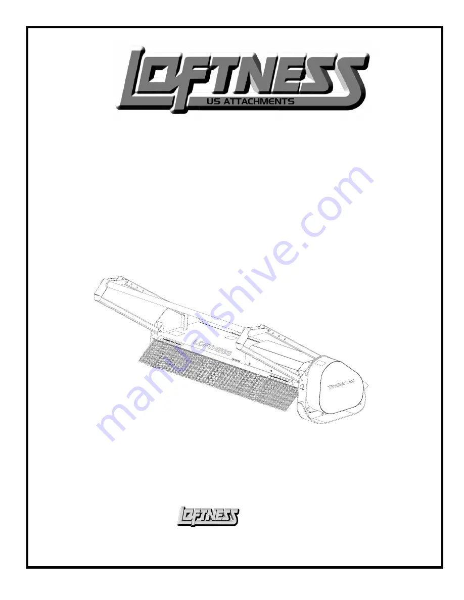
background image


Timber Ax 


Skid-steer Mounted Tree Shredder                 


43AXH     53AXH     63AXH     73AXH     83AXH      


Operator’s Manual & Parts Book 


                                       (2004) 


                                     Model Number: _________________ 
                                     Serial Number: 

 01-100 Thru 01-168


                                     Date of Purchase: ________________ 


Specialized 

                                                                                                        Equipment, Inc.


 650 So. Main Street  -  PO Box 337 - Hector, MN 55342 

Business Phone: 320-848-6266    *    Fax:  320-848-6269    *    Toll Free: 1-800-828-7624


N14867                                                                                                                                                                            January, 2004 


Summary of Contents for 43AXH

Page 1: ...s Manual Parts Book 2004 Model Number _________________ Serial Number 01 100 Thru 01 168 Date of Purchase ________________ Specialized Equipment Inc 650 So Main Street PO Box 337 Hector MN 55342 Business Phone 320 848 6266 Fax 320 848 6269 Toll Free 1 800 828 7624 N14867 January 2004 ...

Page 2: ...ide years of dependable service when proper use and maintenance is adhered to The potential for misuse in many applications exists therefore a limited warranty is provided as follows All Shredders Rotor Balance Critical rotor balance can be affected by conditions beyond LOFTNESS control such as the operation of a shredder beyond the Company s rated capacity improper knife replacement missing knive...

Page 3: ...s 1 1 Safety Instructions for Operation 1 2 Section 2 Operating Operating Instructions 2 1 Set up 2 1 Section 3 Maintenance Lubrication 3 1 General Service 3 1 Storage 3 2 Trouble Shooting 3 3 Torque Chart 3 4 Section 4 Service Parts Service Parts Ordering 4 1 Return Policy 4 1 Decals 4 2 Parts Lists and Drawings 4 5 ...

Page 4: ...tions and or laws and in compliance with on product labeling and these instructions Make sure that all personnel have read this owner s manual and thoroughly understand safe and correct operating installation and maintenance procedures Provide impact resistant shielding on the power unit to protect the operator from the possible dangers of flying debris Make sure the shredder is set up correctly b...

Page 5: ...Section 1 Safety ...

Page 6: ...YEWEAR IS ABSOLUTELY MANDATORY for operator and others in the work area Due to the possible danger of flying debris it is ABSOLUTELY MANDATORY that IMPACT RESISTANT SHIELDING be provided on the power unit to protect the operator The owner is responsible for providing the operator protection devices on the power unit ...

Page 7: ...ering on yellow background Refers to a potential hazard or unsafe practice which may result in minor personal injury The following safety information is a general overview of precautions that should be adhered to 1 Read this manual carefully Become thoroughly familiar with the controls and proper use of the machine Insure that all operators know how to stop the unit by disengagement of the control...

Page 8: ...nd other workers off and away from the machine while it is operating or engine is running Do not carry passengers Before inspecting cleaning lubricating adjusting or servicing any part of the brush shredder always exercise the Mandatory Shut Down Procedure page 1 2 Section 1 After service has been performed be sure to restore all guards shields and covers to their original position Read and observ...

Page 9: ...f equipped when operating the brush shredder Never operate the brush shredder in a lifted position Work only on the surface that the loader is standing on Do not operate the mower above the rated RPM DANGER DANGER Before leaving the operator s position for ANY reason or allowing anyone near the brush shredder always exercise the following Mandatory Shut down Procedure page 1 2 Section 1 Operation ...

Page 10: ...empt to use hands to search for suspected oil leak If injured by escaping fluid consult a doctor at once Serious reaction or infection can occur if proper medical treatment is not obtained immediately WARNING Never operate the shredder without guards shields plates or other safety precaution devices in place Shields are for your protection please keep all shields in place Always cut in an up and d...

Page 11: ...Section 2 Operating ...

Page 12: ...YEWEAR IS ABSOLUTELY MANDATORY for operator and others in the work area Due to the possible danger of flying debris it is ABSOLUTELY MANDATORY that IMPACT RESISTANT SHIELDING be provided on the power unit to protect the operator The owner is responsible for providing the operator protection devices on the power unit ...

Page 13: ...Loftness Hydraulic Brush Shredder can be attached to any skid steer with an auxiliary hydraulic system of 21 54 GPM which has a standard universal skid steer hitch Operating Speed Various mowing conditions and desired finished cut appearance will determine proper ground speed Heavy brush will require a forward stop and go movement to allow the shredder to properly mow the brush WARNING Do not oper...

Page 14: ...must extend through the holes in attachment mounting plate Levers must be fully down in the locked over center position Failure to secure wedge pins can allow attachment to come off causing serious injury or death Connect hydraulic quick couplers from flail mower to auxiliary hydraulic outlets on loader Belt Tension The rotor drive belts should have 1 2 maximum deflection at the midpoint between t...

Page 15: ...Section 3 Maintenance ...

Page 16: ......

Page 17: ...nife is replaced the knife on the opposite side of rotor must be replaced to maintain the balance 1 Refer to page 4 8 in Section 4 for an illustrated parts listing 2 Remove the 5 8 UNF bolt lock nut and knife 3 Install new knives bolt must be inserted through the knife mount from the rotor side to allow the nut to be on the outside 4 Apply a thread locking compound to the nut and tighten to torque...

Page 18: ...d with the mower in operating position but the procedures for rotor removal and installation are greatly simplified if the machine is turned upside down CAUTION If procedure is initiated with mower in operating position proper lifting devices must be used to lift and move rotor A mower rotor weighs approximately 100 lbs ft i e a 73 inch mower rotor weighs approximately 608 lbs Rotor Removal Mower ...

Page 19: ...rocedure for installation Storage End of the Season Clean entire mower thoroughly Clean the belt and pulleys relax the belt tension Lubricate all parts of the machine see lubrication page 3 1 Section 3 Make a list of all worn or damaged parts and replace them Paint all parts that are worn or rusted Store mower in a clean dry area Review your operator s manual Beginning of the Season Review your op...

Page 20: ...Vibration Broken or missing knife Replace knife Mud and or debris wrapped around Clean the machine the rotor Bearing malfunction Check and replace faulty rotor and drive line bearings Damage to rotor includes bent end Return to factory for repair of shafts missing balance weights or actual rotor deformity from striking rocks etc Uneven Cut Knives dull or worn excessively Reverse or replace knives ...

Page 21: ... 1 4 55 6 2 72 8 1 86 9 7 112 13 121 14 157 18 61 6 9 86 9 8 5 16 115 13 149 17 178 20 229 26 250 28 324 37 125 14 176 20 3 8 17 23 22 30 26 35 34 46 37 50 48 65 19 26 26 35 7 16 27 37 35 47 42 57 54 73 59 80 77 104 30 41 42 57 1 2 42 57 54 73 64 87 83 113 91 123 117 159 45 61 64 88 9 16 60 81 77 104 92 125 120 163 130 176 169 229 65 88 92 125 5 8 83 112 107 145 128 174 165 224 180 244 233 316 90 ...

Page 22: ... ZnCr W CL 8 8 Plated Plated Plated Bolt Silver Gold Silver Gold Silver Gold M4 15 107 19 2 2 23 2 6 30 3 4 33 3 7 42 4 8 16 1 8 M6 51 5 8 67 7 6 79 8 9 102 12 115 13 150 17 56 6 3 M8 124 14 159 18 195 22 248 28 274 31 354 40 133 15 M10 21 28 27 36 32 43 41 56 45 61 58 79 22 30 M12 36 49 46 63 55 750 72 97 79 107 102 138 39 53 M16 89 121 117 158 137 186 177 240 196 266 254 344 97 131 M20 175 237 2...

Page 23: ...Section 4 Service Parts ...

Page 24: ......

Page 25: ...ne orders in writing 2 Inspection of parts when received is important Damages or shortages should be brought to the attention of the carrier at the time the parts are accepted Shipper s responsibilities cease upon delivery of shipment in good order to the customer Return Policy Return of parts for either warranty or incorrect parts received must have a Return of Materials Authorization RMA number ...

Page 26: ...ease 3 required 4138 F E M A 1 required 4189 Warning Rotating Parts 1 required 4334 Danger Stay Back 1 required N12684 Small 3D Loftness 1 required N13517 Made in the USA not shown 1 required N13721 Model Serial Number Tag 1 required N13863 Danger Flying Debris 1 required N13864 Timber Ax 2 required N13872 Rotation 1 required N12684 4137 4334 4138 4189 Model Number Serial Number N13872 4135 N13721...

Page 27: ......

Page 28: ......

Page 29: ......

Page 30: ......

Page 31: ......

Page 32: ......

Page 33: ......

Page 34: ......

Page 35: ......

Page 36: ......

Page 37: ......

Page 38: ......

Page 39: ...1 Gauge 0 6000 PSI Pressure N13879 1 Bushing Mounted on Gauge N13880 1 Bushing Mounted on Gauge N A 2 Caps Aluminum Bushing Covers N13996 1 Gauge Angle Knife N A 1 Tube Loctite Small N14867 1 Operator s Manual Parts Book Warranty Included 4187 6 Pin 3 4 x 4 1 4 Plated 4099 4 Pin Cotter 1 8 x 1 1 2 4336 2 Clip Hairpin 1 8 x 2 1 4 N16279 1 Case Protective Gauge To order the Diagnostic Gauge Kit only...

Page 40: ...motor mount Note It may be necessary to grind a corner off the head of the 1 1 4 bolts to allow clearance for installation into the lower 2 holes of the motor mounting flange 5 Install 4 1 1 2 x UNC Gr 8 bolts in the remaining 4 mounting holes Use a thread locking compound to assure that all 6 bolts will stay securely fastened 6 Using a staggered pattern tighten all 6 bolts to 50 ft lbs of torque ...

Page 41: ... 34 2163 1673 35 2227 1722 36 2290 1771 37 2354 1821 38 2114 1635 39 2170 1678 40 2225 1721 41 2281 1764 42 2337 1807 43 2126 1644 44 2175 1682 45 2225 1720 46 2274 1759 47 2323 1797 48 2373 1835 49 2232 1726 50 2277 1761 51 2323 1796 52 2368 1832 53 2414 1867 54 2459 1902 55 2168 1676 56 2207 1707 57 2246 1737 58 2286 1768 59 2325 1798 60 2365 1829 27 2038 1576 28 2113 1634 29 2188 1693 30 2264 1...

Page 42: ...A is the return line back to the loader If possible route the hoses down the back of the machine to a point even with the mounting plate hinge point then back up to the outlets This allows the hoses to bend at the hinge point rather than stretching shortening and getting tangled as the machine is rotated Secure with straps to avoid pinch points 4 Start machine and check that rotor shaft is rotatin...

Reviews: