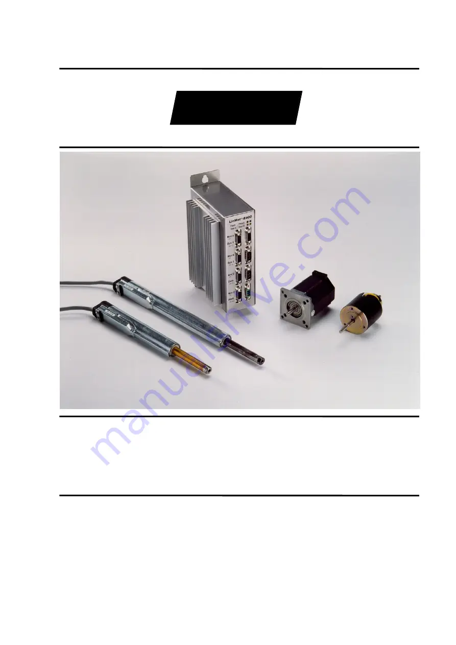
background image


LinMot


User Manual 

Rel. 1.0 


Tel.: +41 (0)56 419 91 91 

Fax: +41 (0)56 419 91 92 

Email: [email protected] 

Homepage: www.linmot.com 

NTI AG 
LinMot 
Haerdlistrasse 15 
CH-8957 Spreitenbach 

Summary of Contents for E

Page 1: ...LinMot User Manual Rel 1 0 Tel 41 0 56 419 91 91 Fax 41 0 56 419 91 92 Email office linmot com Homepage www linmot com NTI AG LinMot Haerdlistrasse 15 CH 8957 Spreitenbach ...

Page 2: ...in whole or in part without the prior written consent of NTI AG LinMot is a registered trademark of NTI AG Note The information in this documentation reflects the stage of development at the time of press and is therefore without obligation Sulzer Electronics reserves itself the right to make changes at any time and without notice to reflect further technical advance or product improvement Please ...

Page 3: ...nterruption ____________________ 3 9 3 8 Operation and configuration ____________________________3 10 3 8 1 System configuration _____________________________________ 3 10 3 8 2 Curve generation ________________________________________ 3 11 3 8 3 Monitoring function digital Oscilloscope ____________________ 3 12 3 8 4 Error logbook___________________________________________ 3 13 3 9 Customer speci...

Page 4: ..._______________________5 3 5 5 Commander___________________________________________5 4 5 6 Control Panel__________________________________________5 4 5 7 Parameter Inspector____________________________________5 5 5 7 1 Editing the parameters _____________________________________ 5 6 5 7 2 Saving and loading parameter sets____________________________ 5 7 5 7 3 Copy and Paste________________________...

Page 5: ... 12 4 Oscilloscope configuration for the following error monitoring _____ 5 27 5 12 5 Final remark____________________________________________ 5 28 5 13 Tutorial C Generating reference curves _________________5 29 5 13 1 Linear Out curve_______________________________________ 5 30 5 13 2 Hold curve ___________________________________________ 5 32 5 13 3 Jump Back curve ____________________________...

Page 6: ...unit Further the interfaces and the installation are described in this chapter This information helps you optimally embed the LinMot products in your application In this chapter you will get accustomed with the functionality and possibilities of the PC software for the configuration of the LinMot electronic unit Further you will find examples that will make the first commissioning of the system ea...

Page 7: ...nformation that should make operating the devices easier is given here Caution Non observance of these warnings can represent a danger for health or life and lead to damage or destruction of the devices and other objects Strong magnetic fields Warning about magnetic materials that could cause damage to magnetic data mediums like diskettes credit cards etc ...

Page 8: ...he safety of the plant to execute the necessary work and thereby recognize and prevent possible danger The operation manual as well as any further manuals in the documentation of the product are to be followed consequently when executing the respective operations Only tested and potential separated power supplies are allowed to be used for the voltage supply of the LinMot electronic units and othe...

Page 9: ...ts are intended to be embedded in other machines The ultimate mode of action is only defined once these components have been embedded in the user s machine or plant The conformity of the construction with the existing prescriptions and laws lies under the sole responsibility of the user The commissioning of the components is only permitted in machines or plants that comply with the CE machinery gu...

Page 10: ...ngineers and draftsmen from electrotechnical detail questions and allow for quick and function oriented work Among the actuators connectable to the LinMot electronic units the electromagnetic direct linear drives LinMot P take a special position as they offer completely new possibilities in the machine construction and mechatronic system concept The notions LinMot Step and LinMot Magnet refer to c...

Page 11: ...ced with the use of LinMot Magnet by driving them over excited during the transient 3 2 LinMot P a new construction element Most commercially available servo drive systems only dispose of rotating motors where the speed and in some cases the angular position are controlled However many applications don t only need rotational movements but linear movements too The conventional solution is to realiz...

Page 12: ... intervention in the mechanic 3 3 Substitution possibilities of LinMot P Depending on the application LinMot P can substitute the following conventional solutions and extend them with additional functionality due to its complete electronic control Spindle drives Cam disks Mechanical levers Belt drives Pneumatic cylinders Rack and pinion drives ...

Page 13: ...ot P The linear drives LinMot P can be used both as stand alone systems or in connection with highly complex machines The following list of application examples is therefore not complete and gives only an insight in the variety of the possible applications Textile machines Weaving machines knitting machines carpet machines winding machines Packaging machines Food pastries coffee tee sweets Consume...

Page 14: ...ge Power circuitry supply Signal circuitry supply Ref position Power Power Position Temp Power Position Temp Power Filter Position Control Current Control Velocity Control Commutation Sensor Processing Power Ampl PWM Curves Reference Position Position Temperatur Power Position Temp Position Temp Figure 3 3 LinMot s peripheral position control frees the higher level control system from calculation ...

Page 15: ...utputs position set values online for the motor to follow smoothly Solution Operating mode analog with vmax amax filter activated s t a amax t amax LinMot E LinMot P s PC PLC mode analog analog out analog out t 3 Example Digital selection between two set values Following a digital high low signal from a PLC the motor moves between two given positions with presettable maximum acceleration and speed...

Page 16: ...s a previously defined curve cyclically with a given frequency Solution Operating mode Continuous Curve Acceleration limiter and speed limiter set to the desired maximal values digital out t high low s t LinMot E LinMot P s PC PLC mode continuous digital out 6 Example Synchronization on a speed value A linear movement should be executed from a particular point and with a previously defined speed S...

Page 17: ...max t vmax LinMot E LinMot P s PC PLC mode two position digital out 3 6 3 Connection to higher level control systems The electronic units LinMot E can be controlled by higher level control systems directly by means of analog or digital input output signal lines The necessary parameterisation is done with the LinMot Talk software via an RS 232 connection Networking via CAN bus or RS 232 is also pos...

Page 18: ...error monitoring Position range monitoring 3 7 3 Emergency stop possibilities From the point of view of the higher level control system there are two ways to handle the LinMot actuators in case of an emergency stop With the so called FREEZE signal the drives can be stopped and maintained in their current position The movement is resumed when the FREEZE signal becomes inactive again By means of the...

Page 19: ...early selected and edited with LinMot Talk by simple clicking with the mouse As all the parameters are stored in the electronic unit they can be recalled analyzed and changed at any time Creating duplicates of parameters and parameter files to be archived is equally easy Password protection protects the data from illegitimate access Figure 3 5 Parameter Inspector window Import Export Check Print L...

Page 20: ...ignals in different operating modes The shapes of these curves can be generated automatically by means of the Curve Creator or can be edited manually point by point as Excel tables Figure 3 6 Reference curves can be generated semi automatically Curve definitions Graph Curve parameters Edit buttons Close buttons Graph buttons ...

Page 21: ...ensors etc The differences between the two curves can give indirect hints on counteracting forces and friction forces which can be useful when adjusting the controller parameters The operation and look of the monitoring function correspond to those of modern digital oscilloscopes Figure 3 7 Motion analysis with the integrated digital Oscilloscope File control panel Print control panel Variables pa...

Page 22: ...lectronic units the errors that have occurred during operation can be logged on a time basis The information is stored in the non volatile memory and allows a later reconstruction of the events Figure 3 8 Error messages are saved to the logbook for later analysis Error display Error list Actual errors Actual warnings ...

Page 23: ...rried out by the manufacturer In most cases the customer specific changes will be realized in the software of the electronic unit Customized Application Software In most cases this will relate to the following two requirements Additional control functions Networking with customer specific bus systems CAN Bus RS 232 Basic Application Software Firmware LinMot Standard Software Basic Application Soft...

Page 24: ...lectronic units please read the manual for SW Rel 1 3 4 1 Operating modes A wide range of operating modes are available for driving setting the reference values the actuators connected to the electronic unit The desired set values can be given directly through an analog interface or else they can be stored in the electronic unit in form of curves and tables that can be run on a digital trigger sig...

Page 25: ...sition definition In applications where the movement has to be executed with a controlled acceleration the enormous acceleration capabilities of the linear drives of the LinMot series can be a disturbing factor For this reason the maximal allowed acceleration and speed for each motor can be specified individually This way the slider will accelerate within the limits of the application even on jump...

Page 26: ...e load is given by the higher level control system directly through an analog input signal Figure 4 4 Analog current setting In the electronic unit a current range can be freely defined that will correspond to the 0 10V range of the analog signal from the interface 4 1 3 Two point run The operating mode Two point trigger is the simplest way to drive the actuators from the higher level control syst...

Page 27: ...igger signals In the electronic unit two reference curves are stored for each actuator one for the Low High state change and one for the High Low state change of the trigger signal When the trigger signal state changes at the input of the electronic unit the corresponding curve is run The electronic unit can store curves with up to 4 000 reference positions Figure 4 6 Running reference curves When...

Page 28: ...efer to the SW Rel 1 3 manual Can Bus interface Normal CAN version with 11 Bit identifier and Extended CAN version with 29 Bit identifier with transfer rates up to 1 Mbaud For special applications Sulzer Electronics AG offers the possibility to implement a specific CAN protocol for the transmission of the set values in the electronic unit Sulzer Electronics AG will be happy to give any further inf...

Page 29: ...he drives RUN The motors run STOP Stop behavior ERROR Error state The following figure shows the states and the possible state transitions LED off LED blinking LED on LED s Fault Ready Stat A Stat B RUN STOP FREEZE DISABLE ERROR WAIT FOR DISABLE DRIVE INIT FREEZE SETUP Figure 4 7 Operating states A state change can either be caused by means of the digital control signals to the electronic unit or ...

Page 30: ... state DISABLE occurs only when the RUN and INIT signals are low 0V This security feature can be disabled in the Auto Start Mode where the system starts automatically DISABLE if the INIT and RUN inputs are not active DISABLE the transition is automatic in the Auto Start Mode ERROR the transition occurs unconditionally when an error occurs 4 2 3 Operating state Disable The actuators remain unpowere...

Page 31: ...rns to the state DRIVE INIT unchanged DISABLE if the RUN input becomes inactive and the INIT input is inactive DRIVE INIT if the RUN input becomes inactive and INIT is active STOP if the STOP signal becomes active ERROR the transition occurs unconditionally when an error occurs 4 2 6 Operating state Stop A transition to this state takes place when the Stop signal becomes active which means the hig...

Page 32: ... a position range These messages are forwarded as a collective message or concatenation from all the actuators connected to an electronic unit 4 3 1 Following error monitoring For the following error monitoring the difference between the position set value and the actual position is monitored If this difference becomes bigger than the maximal allowed position difference that was set it is to assum...

Page 33: ...ctuator is outside the motion range of the second one before moving the latter to it Therefore some feedback is needed when all actuators are within a safe range Figure 4 9 Position range monitoring A position range can be specified for each actuator As soon as an actuator s actual position is outside this range a message is sent to the higher level control system Configuration possibilities ...

Page 34: ... The actual position is still maintained when the linear motor is not powered and the slider is moved from its position Three types of initialization are available for the linear motors of the LinMot P series When initializing the slider is moved with a user definable speed until it encounters a stop As soon as the slider stops its position is taken as the zero position Figure 4 10 Initialization ...

Page 35: ...ified direction to trigger the active edge In this third case no reference run is executed The actual position of the slider upon powerup of the electronic unit is saved as zero position This implies that the slider must already find itself in the desired zero position before powering up the unit After the initialization is done in one of the three modes it is possible to check if the slider can m...

Page 36: ...on The rotor rotates in the specified direction with a user definable speed over the position sensor As soon as the sensor detects the rotor the actual position is saved as the zero position If the trigger signal is already High when the initialization is started the rotor is first moved in the opposite direction until the signal goes low At this point it is moved in the specified direction to tri...

Page 37: ... Com RS 232 TX RS 232 RX GND Figure 4 12 Signal interfaces The interfaces are accessible from the front of the unit through three D Sub connectors SYS1 SYS2 and COM 4 5 1 SYS1 interface The operating states FREEZE and STOP of the electronic unit are driven through the inputs of the SYS1 interface The outputs WARNING OUT ERROR OUT and POSITION ERROR OUT carry internal warnings and error messages to...

Page 38: ...l outputs are realized as open collector outputs and must be driven over an external pull up resistor Figure 4 13 Digital output layout During normal operation no warnings or error messages the digital outputs are pulled down to ground GND by the electronic unit When an error or a warning is generated or the signal cable is interrupted the output becomes high impedance and is pulled up over the ex...

Page 39: ...0 2V DC For signal 1 3 5V DC Input current 20mA 24V Input delay 1 6ms The initialization of the motors is started Data Galvanically separated input High level active Input voltage 0 24V DC max 10 26V DC For signal 0 2V DC For signal 1 3 5V DC Input current 20mA 24V Input delay 1 6ms The inputs TRIG ANALOG IN A TRIG ANALOG IN B TRIG ANALOG IN C and TRIG ANALOG IN A are used in the states INIT and R...

Page 40: ...al interface of a PC for the configuration with the LinMot Talk software Table 4 3 Pin configuration of the COM connector A 9 pole interface cable with 1 1 connections is needed for the connection of the electronic unit to a PC Pin Description Pin Description 1 NC 6 NC 2 RS 232 TX 7 NC 3 RS 232 RX 8 NC 4 NC 9 NC 5 GND ...

Page 41: ...ble on the front of the electronic units of the E100 E200 E400 series for connecting the actuators Table 4 4 E100 E200 E400 pin configuration for the LinMot P Only the special LinMot cable Art No 0150 1920 must be used for extension cables In applications where the motor cable has to be or moved during operation the special trailing chain cable Art No 0150 1927 must be used max 10m 10 pole Mini Co...

Page 42: ... D Pin 1 6 2 7 Rotor Stepper motor E100 E200 E400 Figure 4 14 E100 E200 E400 Connection layout for stepper motors Only shielded cable with a core cross section area of 0 20mm should be used When driven by an electronic unit of the E1000 E2000 E4000 family stepper motors must be connected as shown in the following figure Phase 1 Phase 2 Mot A Mot B Mot C Mot D Pin 1 2 3 4 Rotor Stepper motor E1000 ...

Page 43: ...allowed supply voltage for both the signal and the power circuitry inevitably damages the electronic unit Only tested power supplies featuring potential separation must be used 4 7 1 E100 E200 E400 supply In the electronic units of the E100 E200 E400 series both signal and power circuitry are supplied over the 3 pole POWER SUBCON connector on the front As the devices can be supplied with the same ...

Page 44: ... when driving four linear motors LinMot P at the same time with one E400 electronic unit a power supply of 48V 300W is sufficient 4 7 2 E1000 E2000 E4000 supply In the electronic units of the E1000 E2000 E4000 series the signal circuitry and the power circuitry are supplied over two separate connectors that are found on the front of the unit As the supply voltage ranges for the two circuits are di...

Page 45: ...C power supply see data sheets of the linear motors Table 4 8 Power supply pin configuration E1000 E2000 E4000 Data Input voltage 48 72V DC The required power strongly depends on the loading of the motors For an optimal design of the power supplies the power requirements of each application should be clarified individually Practical applications have shown that in most cases even when driving four...

Page 46: ...iguration The two electronic unit series E100 E200 E400 and E1000 E2000 E4000 differ only in the execution of the power board The signal boards are absolutely identical and for this reason the explanations in this section are valid for both The interfaces to the higher level control system can be configured on the signal board Only the following jumper positions result in usable configurations of ...

Page 47: ...Configuration SYS2 By default the electronic unit is configured for operation with the analog inputs for the set values and the trigger signals The jumper positions for SYS2 must not be changed otherwise the inputs for the set values will no longer be available The Com interface for configuring the electronic unit via the PC software LinMot Talk is normally operated in the RS232 mode Upon request ...

Page 48: ...Mot E200 AT are fitted with a heatsink and should be mounted in vertical position to allow better cooling When mounting the units it is important to take into consideration the fact that the housing temperature can reach 60 heatsink up to 70 Sufficient room for heat dissipation should be provided The power dissipation of the units can vary considerably depending on the application and should be de...

Page 49: ...ans of an additional guide FTrans Figure 4 21 Transversal loads The linear drives of the LinMot P series are intended exclusively for operation as drive elements and are not allowed to be used as guide or bearing elements In all constructions where the slider of the LinMot P drives is used to move another longitudinally sliding machine part over direct coupling an over determinate system arises Fi...

Page 50: ...cause damage to magnetical data medium or sensitive electronic devices by merely coming close to them When manipulating the sliders hitting them against iron parts tools etc must be absolutely avoided as this can lead to permanent damage of the slider surface damage bending Further hitting against other ferrous objects represents a danger of injury Bruised fingers etc The slider of the LinMot P mo...

Page 51: ...curves for the LinMot Electronic Existing curves can be loaded saved merged and printed New curves can be created in a simple way The Oscilloscope helps the user commissioning the LinMot system It allows real time recording subsequent on screen viewing and printing of internal variables like for example position set value and actual value With the Error Inspector the user has the possibility to di...

Page 52: ...eting the installation a new program group appears with the name LinMot Talk The README TXT file contains late breaking notes on the respective version 1 Open the file LINTALK INI with a text editor 1 Remove the semicolons before the serial interface that you plan to use for LinMot Talk You can also have both interfaces activated The following example shows a configuration file in which the COM1 i...

Page 53: ...tronic unit is connected can be selected here Note that only the interfaces that were activated in the Lintalk ini file will be displayed The ID field should contain the name User The correct password must be entered at this point see also the relative notes at the end of this section after which it is possible to log in by clicking on the OK button If the password was entered correctly the Comman...

Page 54: ...it When updating the basis software the new software can be downloaded to the electronic unit with the Load command Figure 5 4 Control Panel window Starts the operating software of the LinMot electronic unit if it is not already running Stops the operating software of the LinMot electronic unit All motors are turned off Executes a hardware reset on the LinMot electronic unit This is only necessary...

Page 55: ...ine modes Import and export of parameter configurations Copy and Paste of parameters and parameter sets Printing of parameter sets Figure 5 5 shows an operating window of the Parameter Inspector The window can be enlarged to make more levels visible The user has also the possibility to navigate the parameter tree with the cursor keys Figure 5 5 Parameter Inspector window Import Export Check Print ...

Page 56: ...ad to small discrepancies between the value that was entered and the value that is actually displayed once it has been transmitted The values entered are rounded to the values that are stored in the electronic unit according to the resolution of the unit Live parameters are actualized immediately on the electronic unit after a change whereas normal parameters are saved to the unit only after a new...

Page 57: ...he electronic unit end with the extension cfg The corresponding file extension must be selected when importing parameter sets When exporting a set the selection is done automatically 5 7 3 Copy and Paste In order to simplify the configuration of several motors the software supports the Copy Ctrl C and Paste Ctrl V commands The copy command copies the parameter actually selected If this is a direct...

Page 58: ...m function that checks the parameter configuration automatically is integrated This function is called by clicking on the Check Configuration button An incorrect or missing parameter setting is marked and displayed so that it can be corrected by the user Subsequent clicking on the check Configuration button causes the display of the next incorrect parameter or a message informing that the paramete...

Page 59: ...Online mode is accessed by logging in and activating the Parameter Inspector from the Commander 5 7 8 Offline mode The Offline mode allows the editing of a parameter configuration that was saved beforehand The electronic unit doesn t need to be connected to the serial interface for this operation Changes to the parameters are not transmitted directly to the electronic unit but the modified configu...

Page 60: ...appears after clicking on the Curve button in the Commander window Figure 5 8 shows a typical Curve Inspector window Figure 5 8 User interface of the Curve Inspector The single operational elements are described in the following chapter 5 8 2 Operational elements of the Curve Inspector All curves that are loaded or newly generated are listed in this window New entries are appended at the end of th...

Page 61: ...e sections is not modified A warning is generated in case the end point of one curve does not correspond with the starting point of the next curve In ceases where not all the curves are specified for the same drive type a warning is also generated When merging curves some points must be interpolated This could lead to minor changes in the curves This effect can be minimised by selecting a higher n...

Page 62: ...ndow are moved to the memory window and appended to the list in the same order Left All the curves selected in the memory window are moved to the curve window and appended to the list in the same order Delete The selected curves are deleted Each modified curve can be saved separately by the user Ctrl C Copies the selected curves in a buffer Ctrl V Pastes the curves in the buffer to the selected cu...

Page 63: ...ys with the help of the Wizards The input possibilities and the interface are adapted accordingly The Curve Editor is used to edit the curves Depending on the type of curve it can have one of the following interfaces Figure 5 9 Manual creation of curves Curve definitions Graph Curve points Edit buttons Close buttons Graph buttons ...

Page 64: ...The elements that are always visible are described first The curve is displayed graphically in this window Changes are displayed immediately for manually edited curves Manual wizard or after a curve calculation for calculated curves The curve can be selected and moved with the mouse Fit View The axis of the graph are scaled automatically to fit the whole curve in the display Print The curve graph ...

Page 65: ...he time as it is calculated If the drive type selected in the creation of the curve does not correspond with the actual drive type the electronic unit will generate an run time error Curve Error when the curve is called Add The number of points that should be added at the end of the curve can be entered in the dialog box that is displayed by clicking on this button The inserted values are set auto...

Page 66: ...owed when the curve is started is defined by Max Start Acc The unit depends on the selected Drive Type Max Start Acc is only visible for the Point To Point wizard Max Stop Acc The maximal acceleration allowed when the curve ends is defined by Max Stop Acc The unit depends on the selected Drive Type Max Stop Acc is only visible for the Point To Point wizard 5 8 5 Creating curves with the wizards Th...

Page 67: ...reation of reference curves can create and or edit curves with the spreadsheet calculation program Excel When editing curves in Excel it is important that the format of the curve files is maintained For this reason this way is only recommended for experienced users Tutorial D shows an example of how curves can be edited with Excel ...

Page 68: ...nMot electronic unit in real time and then transmit it to the PC to be displayed It offers the following functions two independent channels 256 data values for each channel variable sample rate from 400µs to 26 2s various trigger modes Figure 5 11 Working with the Oscilloscope File control panel Print control panel Variables panel Trigger panel Sample rate panel Display panel Start button Graph di...

Page 69: ...ve Figure 5 12 The variables panel 5 9 2 Setting the trigger mode The trigger mode defines when the recording should be started The following trigger modes are available The recording is started when the selected variable exceeds res falls below the threshold specified In Figure 5 13 the trigger is set to start the recording when the actual position of drive A exceeds the given position Figure 5 1...

Page 70: ...percentage A pretrigger of 80 would cause 80 of the recording time to be dedicated to events preceding the trigger condition and 20 of it to be dedicated to events following the trigger In some situations it can be advantageous to start recording data after a certain delay following the trigger condition In the Delayed mode the user can set a value for the delay time It is sometimes possible that ...

Page 71: ... the LinMot electronic unit notifies the PC that the data are ready and available The PC then reads the data from the electronic unit and displays it There are however three exceptions to this behavior When the Multishot function is selected the Start button must be clicked first in order to start the Oscilloscope on the LinMot electronic unit When the desired event occurs the last event recorded ...

Page 72: ...ges contain information about system time state of the basis software drive type and type of error The time is given in the HHHH MM SS format where HHHH is the number of hours MM the number of minutes and SS the number of seconds These buttons control the access to the errors stored in the electronic unit Show The Show command reads the last 16 error entries from the LinMot electronic unit and dis...

Page 73: ...USED TRANSITION TO ERROR STATE shows which error caused the transition to the Error state The section PENDING ERRORS lists all the errors active at the moment of reading If the Show button is clicked when the basis software is not in the Error state nothing appears in the display window Show Clicking on the Show button of Actual Warnings causes the actual warnings to be read and displayed The actu...

Page 74: ...unication can be started by clicking on the OK button After successful login the Commander is displayed The Commander gives access to all the modules of the LinMot Talk program In this example we will use the Parameter Inspector and the Curve Inspector modules 1 By pushing the Param button the Parameter Inspector is started All available parameters are dispalyed hierarchically The user can easily ...

Page 75: ...1000 ms for Time Then we enter six values the first 3 set to 5 mm the others set to 50 mm Figure 5 18 The curve created We now close the curve with the OK button and write it to the electronic unit by moving it in the download window and then clicking Download 5 12 2 Configuring the electronic unit The easiest way is to start from the standard or default configuration This can be imported in the P...

Page 76: ...recording will start as soon as motor A starts executing curve 1 We now switch to the Acquire panel by clicking on Acquire in the lower part of the Oscilloscope window Here we can select the sample rate and the sample mode We set a sample rate of 4000 µs so that we can record approximately a whole period the curve is executed in 1000 ms and the Oscilloscope records 256 values We set the mode to De...

Page 77: ...and errors In order to reduce the changes to a minimum we will use the same motor with the same configuration We want to record the movements of the motor in a case of following error On channel A we leave the setting Actual Pos to Drive A while on channel B we select Demand Pos Filtered on Drive A Demand Pos is the position set value that is read directly from the reference curve As the set value...

Page 78: ...ou can record any variable as for example Current That way you can gain information on the force of the motor 5 12 5 Final remark These two examples were intended to give you an introduction in the operation of the Oscilloscope In order to become even more accustomed with this tool it is advisable to test different settings for example recording and defining other curves and motors or combinations...

Page 79: ...nected to the Mot A port The LinMot electronic unit is connected to the PC LinMot Talk is running on the PC and the user has logged in We create a curve that looks like the following Figure 5 21 Goal of the example The curve is built from three curve sections that we will first define separately Afterwards we will join the three curves together and create our complete work In the end we will let t...

Page 80: ...now make sure that LinMot Pxx 23 is selected as Drive Type If you wish to realize this example with a Pxx 37 choose LinMot Pxx 37 as Drive Type In the following this alternative will only be shown between parenthesis We change the name to Linear Out At this point the actual movement sequence is defined We want to create a curve that executes a linear movement from 5 mm to 50 mm in one second For t...

Page 81: ...appears Figure 5 23 Dialog box for the number of points The number of points can be increased at this stage in case the accuracy of the Time entry is insufficient for the application We make do with two points and click on the OK button The defined curve should look like this Figure 5 24 Linear Out curve With the OK button we close the Curve Editor and see the curve Linear Out in the curve window ...

Page 82: ...zard to Manual the Drive Type to LinMot and enter Hold in the curve name field We enter a time of 500 ms and twice 50 mm in the value fields In order to increase the accuracy of the actual time we raise the number of points to 8 For this purpose we click on the Add button enter the number 6 when asked and click on the OK button The inserted points will automatically take the value 50 mm The curve ...

Page 83: ... and the End Point to 5 mm We then define the maximum allowed speed of 0 1 m s The maximum start and stop accelerations can be set separately We set max Start Acc to 0 6 m s2 and max Stop Acc to 0 3 m s2 After clicking on the Calculate button the Curve Inspector suggests 32 points for the curve which we accept by clicking OK The time required for the execution of the curve is calculated automatica...

Page 84: ...s we can open the file with the Open button We now have the same curves in the left and right panels of the Curve Inspector window 5 13 5 Merging curves By saving a number of curves to a file the single curves remain separated Should it be required to join the curves to a single continuous movement this can be done by means of the Join command Before we do this we must move the Jump Back curve bac...

Page 85: ...LinMot Configuration Software User Manual V1 01 5 35 Figure 5 28 Motion curve We close the Curve Editor with OK ...

Page 86: ... curves in the electronic unit This is done by clicking on the Download button and confirming the process with OK The curves are now being written to the electronic unit Finally we test the curves For this the electronic unit must be configured correctly We load the standard configuration by clicking on Import and selecting the one appropriate for the electronic unit we are using For an E400 this ...

Page 87: ...s purpose we create two new curves one named Exponential with 16 points and 1000 ms as time and the second one named Triangle with 3 points and 1500 ms Both curves are created with the Manual wizard and the motor selected should be LinMotPxx 23 or LinMotPxx 37 depending on what you are using These two curves are then saved together in a file named ExelTest csv At this point we start Excel and open...

Page 88: ...umn A we enter the following function An ROUND Bn 0 in order to eliminate the decimal point With this the Exponential curve is complete For the Triangle curve we enter the values 50 2000 and 50 manually You should now see the following table Figure 5 31 The curves defined in Excel In order not to loose the formulas in the table it is important to save the table as xls We save the document as ExelT...

Page 89: ...ssibilities in Excel Some are listed here briefly Changing the number of points in a curve by inserting or deleting Calculating the time with formulas Renaming curves Changing motor type Inserting or deleting entire curves Defining and calculating complex curves with special macros ev interactive It is important that the structure of the file remains unchanged curve header values and the keyword E...

Page 90: ...LinMot Parameters User Manual V1 01 6 1 6 Parameters Refer to User Manual for SW Rel 1 3 ...

Page 91: ...LinMot Service Benutzerhandbuch V1 01 7 1 Sulzer Electronics AG 7 Service Refer to User Manual for SW Rel 1 3 ...

Reviews: