Linksys LAPN300, User Manual
The Linksys LAPN300 is a powerful wireless access point designed to expand your network coverage. With its intuitive interface, configuring this device is a breeze. Ensure a seamless installation and setup process by referring to the comprehensive User Manual available for free download at manualshive.com.
Share
Download


Reviews:
No comments
Related manuals for LAPN300
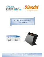
KA300
Brand: Kasda Pages: 42

AP-90M
Brand: Icom Pages: 2

QN-H-220
Brand: Quantum Pages: 8

QN-I-200
Brand: Quantum Pages: 21

QN-I-200
Brand: Quantum Networks Pages: 27

HT-TM01 TripMate
Brand: Hootoo Pages: 47

WTS-10KW-3P
Brand: wattsonic Pages: 60

YFGW520
Brand: YOKOGAWA Pages: 45

Orbi PRO SRS60
Brand: NETGEAR Pages: 2

CS374U-APP
Brand: Pioneer Pages: 12

SMC7904WBRAS-N
Brand: SMC Networks Pages: 2

barricade SMCWBR14-G2
Brand: SMC Networks Pages: 130

MR57
Brand: Cisco MERAKI Pages: 27

ARS-7235-PSE-AC Series
Brand: ANTAIRA Pages: 24

9200
Brand: Kaba Pages: 2

TCSK-01
Brand: TCS Pages: 16

SC20-WL
Brand: Quectel Pages: 87

BT3038
Brand: TECOM Pages: 55


