Link EXT40-4KECO, User Manual
The Link EXT40-4KECO comes with a comprehensive user manual that provides detailed instructions for optimal usage. It is available for free download at manualshive.com, making it easily accessible to users. This manual ensures a smooth experience with the product, offering guidance on setup, operation, and troubleshooting.
Share
Download


Reviews:
No comments
Related manuals for EXT40-4KECO

XPRESSKIT GM9
Brand: Directed Pages: 16

DB-850G
Brand: Dynablend Pages: 32

AV-GM04G3-S1
Brand: SIIG Pages: 14

6350-SR
Brand: Digi Pages: 89

DMEX1
Brand: Dome Pages: 14

HDEXWIR
Brand: Vanco Pages: 12

NC14004-B713
Brand: Fujitsu Pages: 31

Smoothie Concert Mini SB240 Series
Brand: Kenwood Pages: 9

KSB465ER0
Brand: KitchenAid Pages: 3

KHBC10 Series
Brand: KitchenAid Pages: 8

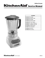
KSB465
Brand: KitchenAid Pages: 44

KHB2351
Brand: KitchenAid Pages: 40
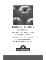
KHB2561
Brand: KitchenAid Pages: 64

KHBC208
Brand: KitchenAid Pages: 44

KSB354
Brand: KitchenAid Pages: 44

KSB560AQ - Martha Stewart - Collection Blender
Brand: KitchenAid Pages: 3

KSB540OB
Brand: KitchenAid Pages: 7
KSB540ER0
Brand: KitchenAid Pages: 12


