background image

                
      



     



            

 

  
     

 

 

https://www.besttruckmanuals.com/

Summary of Contents for T20 AP

Page 1: ...https www besttruckmanuals com...

Page 2: ...https www besttruckmanuals com...

Page 3: ...https www besttruckmanuals com...

Page 4: ...https www besttruckmanuals com...

Page 5: ...https www besttruckmanuals com...

Page 6: ...https www besttruckmanuals com...

Page 7: ...https www besttruckmanuals com...

Page 8: ...https www besttruckmanuals com...

Page 9: ...https www besttruckmanuals com...

Page 10: ...https www besttruckmanuals com...

Page 11: ...Service Training Section 1 Page 1 1 TRACTIONMOTOR https www besttruckmanuals com...

Page 12: ...e motor unit support Electrohydraulic brake mounted directly on the motor shaft Motor without maintenance controlled by 1 speed sensor 1B2 1 temperature probe 1B6 1 2 TECHNICAL DATA Asynchronous motor...

Page 13: ...Flange 2 Circlips 30 x 1 5 FST DIN 471 3 Key 8 x7 x 20 DIN 6825 4 Circlips 25 x 1 2 FST DIN 471 5 Ball bearing 6006 2 RS1 C3GJN DIN625 6 Circlips 55 x 2 FST DIN 472 7 Crown wheel for measuring the spe...

Page 14: ...nnector 1X25 1B6 3 Speedsensorconnector 1X2 1B2 4 Screw CHC M6 X 20 quantity 8 Tighteningtorque9 5Nm 5 O ring 6 Electrohydraulicbrake 7 Brake mounting bolt quantity 3 Tighteningtorque9 5Nm 8 Reduction...

Page 15: ...s recommended to wear gloves Installing the traction motor To install the traction motor proceed in the reverse order as for removal Replace the O ring 5 and grease it before refitting the motor 1 in...

Page 16: ...Service Training Section 1 P ge 6 https www besttruckmanuals com...

Page 17: ...Service Training Section 2 Page 1 2 DRIVE TRANSMISSION https www besttruckmanuals com...

Page 18: ...ar motor 7 which positions the turntable Motor wheel 6 powered by a single stage reduction gear 5 and a conical ring gear Asynchronous 3 kw traction motor 1 mounted vertically on the reduction gear 5...

Page 19: ...the end of the motor spindle Fasten 1 sling 11 and stretch it slightly with the hoist Unscrew the 4 fixing screws 9 of the motor chassis support unit Extract the entire drive unit carefully from the b...

Page 20: ...T20 T24 Loadonthe drive wheel 1 5 T maxi Numberofteeth slewring 108 Speed reducing ratio 19 67 Oil volume 1 5 litres Maximum torque at the wheel static 1 375 Nm Maximum torque at the wheel dynamic 916...

Page 21: ...nggear 17 Drainplug 18 Drain plug joint 19 Trolleywithtaperedrollers 20 Cover 21 Wheel shaft 22 Trolleywithtaperedrollers 23 Spacer 60 7 5 24 Shim 25 Seal ring mounted with loctite 574 26 Wheel bolt t...

Page 22: ...Tighteningtorque9 5Nm 6 ScrewsChcM10X30 quantity 8 Tighteningtorque64Nm 7 ScrewsChcM10X35 quantity 4 Tighteningtorque64Nm 8 Driveunit supportplate 9 Shim forrubberornon brandedrubberdrivewheel 10 Scr...

Page 23: ...on motor and the reduction gear are heavy Use handling gloves to disengage the motor and the reduction gear from the chassis To reinstall the reduction gear proceed in the reverse order as for removal...

Page 24: ...Service Training Section 2 Page 8 https www besttruckmanuals com...

Page 25: ...https www besttruckmanuals com...

Page 26: ...https www besttruckmanuals com...

Page 27: ...https www besttruckmanuals com...

Page 28: ...https www besttruckmanuals com...

Page 29: ...https www besttruckmanuals com...

Page 30: ...https www besttruckmanuals com...

Page 31: ...https www besttruckmanuals com...

Page 32: ...https www besttruckmanuals com...

Page 33: ...https www besttruckmanuals com...

Page 34: ...https www besttruckmanuals com...

Page 35: ...https www besttruckmanuals com...

Page 36: ...https www besttruckmanuals com...

Page 37: ...https www besttruckmanuals com...

Page 38: ...https www besttruckmanuals com...

Page 39: ...https www besttruckmanuals com...

Page 40: ...https www besttruckmanuals com...

Page 41: ...https www besttruckmanuals com...

Page 42: ...https www besttruckmanuals com...

Page 43: ...https www besttruckmanuals com...

Page 44: ...https www besttruckmanuals com...

Page 45: ...https www besttruckmanuals com...

Page 46: ...https www besttruckmanuals com...

Page 47: ...https www besttruckmanuals com...

Page 48: ...https www besttruckmanuals com...

Page 49: ...https www besttruckmanuals com...

Page 50: ...https www besttruckmanuals com...

Page 51: ...https www besttruckmanuals com...

Page 52: ...https www besttruckmanuals com...

Page 53: ...https www besttruckmanuals com...

Page 54: ...https www besttruckmanuals com...

Page 55: ...Section 6 Page 1 Service Training 6 ELECTRICALEQUIPMENT https www besttruckmanuals com...

Page 56: ...Service Training Section 6 Page 2 https www besttruckmanuals com...

Page 57: ...d rail 6Km h Speedreduced onturning 6Km h Speed reduced anti crush 1S3 activated 4Km h Speed reduced battery unlocked 2Km h Speed reduced stabiliser oil level too low 2Km h 6 1 1 2 Tiller rear safety...

Page 58: ...Service Training Section 6 Page 4 6 1 2 Electric plate https www besttruckmanuals com...

Page 59: ...Traction and hydraulic controller LAC 1A1 13 Key switch S1 14 Emergency stop button 7S1 7S5 15 Power fuse LES 3F1 16 Power fuse LAC 1F1 17 Control fuse 1F3 Inclinometer support A1 connector 1X3 tille...

Page 60: ...controlling when each of the six MOSFETS is activated or deactivated it is possible to control in one direction then in the other the current in each of the three motor windings phases MOTORWINDING P...

Page 61: ...tionmotorwill seean AC frequencyof180Hz at themaximumspeed while the MOSFETS will be switched at ON and OFF status at 8 KHz MOTORRUNNINGAT SEMI SPEED A SINGLEPHASESHOWEDFOR REASONSOF CLARITY MOTORRUNN...

Page 62: ...yappliedis low the average ACvoltage applied to themotorwindingsis alsolow On pressing the accelerator initially the voltage and the AC motor frequency will be low Gradually as the truck speed grows t...

Page 63: ...ng is 100 A 2 The nominal power of the battery main fuse 1F1 is 225 A 3 1F3 7 5A Key switch traction hydraulic and steering control circuits NOTE Although this control fuse might be interchangeable wi...

Page 64: ...r and control parts ThenumericcontrolmoduleLTCusestwomicroprocessors TractionandHydraulic thatareauto controlled Ifafault occurs itisdetectedinstantlyand thecontrol systemputsthetruckinsafety whichcan...

Page 65: ...nternaltransistor 29 BK 29 Traction Traction speed reduction no 1 Connected to the battery negative 0V 30 BK 30 Traction Seat Connected to the battery negative 0V 31 WH 31 Traction Platform Connected...

Page 66: ...n and hydraulic are supplied in 5V by a second regulator The two controllers start and launch the LAC internal test program If there is no serious internal fault at the LAC the start up conditions are...

Page 67: ...ng MECHANICAL LINK SUPPLY AFTER THE KEY AND 7S5 Connector 7X9 Terminal Colour Function 1 BN Microswitch input 7S5 2 GY Microswitch output 7S5 EMERGENCY STOP 7S1 7S5 Safety relay 24V 24V Power Auxiliar...

Page 68: ...1 means that the input is linked to the battery negative Value 0 means that the input is disconnected A means that the value can be 1 or 0 Reaction of the truck when you go from one status from 1 to...

Page 69: ...ncy it is enough to press the tiller downwards in horizontal position The microswitch 1S4A opens and disconnects the terminal 1X1 7 The tiller base microswitches are replaced by a wire to the connecto...

Page 70: ...se 16 BN Tiller base signal output negative 6 1 7 Control module tiller in version AP Handlebar in version SP A1 6 1 7 1 Description The control unit is identical to the old range of trucks and is com...

Page 71: ...ARD Potentiometer 1B1 Horn 4 S 1 Lower 2 S 7 Raise 2 S 6 Safety 1 S 3 Rear switch 1 S 22 Circuit A1 Connector 16 channels 1X5 LBS C screws 2 9x6 5 DIN7981 Front switch 1 S 21 Green wire Red wire Yello...

Page 72: ...mum speed 2 to 0 98 to 100 Power supply harness breaks outside range 6 1 7 3 Tiller rear safety control 1S3 The anti crash is available in the AP version This safety works when the truck is in walkie...

Page 73: ...fork arm the hydraulic pressure in the lifting jacks activate the piston and increase the braking The brake release is done by the action of the accelerator to enable start up on side without the tru...

Page 74: ...to the controller LES where they are processed to determine the speed and the direction of rotation of the traction motor No regulation is provided for the speed sensor CAUTION If the sensor is not m...

Page 75: ...nces when it is too high If the motor temperature exceeds 160 C the truck speed is reduced to 2Km h If the temperature probe is defective or if the harness is disconnected the LAC controller will redu...

Page 76: ...en the truck takes a curve the external stabiliser spring crashes at the turn and the truck bends This tilt is detected by an inclinometer the LAC controls the closing of the valve that blocks the sta...

Page 77: ...n negative by the Mosfet transistors When the valves are not fed the stabilisers are free When a valve is fed the corresponding stabiliser is blocked Connector 2X20 Terminal Colour Function 1 RD 73 Po...

Page 78: ...if it is changed or if the LAC is changed No mechanical regulation is possible A 50 value corresponds to a horizontal truck The stabiliser blocking and unblocking thresholds can be controlled with th...

Page 79: ...ng the battery If the truck supply is cut off the valve 2Y7 closed without supply will block the stabilisers 2 If the side output function of the battery is not mounted 2Y7 is replaced by a stopper 1S...

Page 80: ...LAC traction and hydraulic controller The L A C controls the fans when the internal temperature of the power stage exceeds 50 C and stops them when the temperature drops below 40 C Connector 9X11 Ter...

Page 81: ...The horn circuit is supplied directly from the emergency stop contact The push button 4S1 is above the control panel Pressing 4S1 applies a voltage 24V to the horn 4H1 HORN Connector 1X3 Terminal Colo...

Page 82: ...ed with the diagnostics software In the truck standard configuration these speed limitations are deactivated by the controller when the terminals 1X1 29 57 are permanently connected to the battery neg...

Page 83: ...surges and extends the life of the motor Note Putting the traction in safety stops the hydraulic function MOTOR PUMP UNIT 6 2 2 Operating the lowering of the truck initial lift 2Y2 The lowering functi...

Page 84: ...The lift is controlled via 2S6 The fork arms climb Arrives in high position The sensor 1B4 is activated The lift is stopped via 1B4 The lowering function is engaged controlling 2Y2 The fork arms lower...

Page 85: ...position of the set value potentiometer and the position of the wheel potentiometer The motor stops turning when this difference is zero with a certain tolerance range to prevent permanent steering c...

Page 86: ...d a safety CS and a power stage with 4 Mosfet transistors The transistors are controlled by an electronic circuit called DRIVER optocoupled for galvanic insulation located in the power stage If a faul...

Page 87: ...value 13 BU 313 Current signal value track 1 Variable signal between 0V 8 2V 14 WH 314 Speed sensor track B Variable signal 0V 6V 16 WH 316 CAN 1 high steering Connected to the bus CAN 1 high steering...

Page 88: ...nsistor in output 3X1 9 Ub for the line contactor 3K1 The steering contactor 3K1 and the wheel brake system coil F V 7A5 are then fed The power stage is controlled motor at stop outputs M1 and M2 12V...

Page 89: ...LINE CONTACTOR 3K1 AND TRACTION AUTHORISATION 3K1 Characteristics of the line contactor coil Resistance 20 C 44 Ohms Coil interference Diode No series resistance LES LAC Safety relay B 24V 0V Safety r...

Page 90: ...exceeds a steering angle AC hAC on either side of the midpoint of the steering The speed limitation is suppressed when the set value returns to a position less than or equal to the angle AC Beyond 45...

Page 91: ...with propellant controlled by a coil This coil is supplied by a current between 5mA for an almostnegativetorque and750mA forthe maximumtorque The current generated by the LES steering varies accordin...

Page 92: ...obtain redundancy for safety reasons The steering permanently controls the status of each potentiometer by the total of the values of link voltages no 1 no 2 this total must correspond to the supply...

Page 93: ...Section 6 Page 39 Service Training 4 1V 4 1V 8 2V LES https www besttruckmanuals com...

Page 94: ...ecessary This power reset information comes from either a movement of the set value potentiometer variation of the two links in inputs 3X1 3 4 or detection of a truck traction movement by the speed se...

Page 95: ...harge indicator with low level alarm and lifting cut off Important Full load 100 displayed Discharged 0 displayed corresponds to the limit of 80 of battery discharge recharge mandatory Date time Truck...

Page 96: ...trol button 5 Control button 6 Control button 7 Marking of active buttons 8 Display of date 9 Display of time 10 Alarm STOP red 11 Alarm BATTERY red Description Meaning Remarks Screen messages Recharg...

Page 97: ...l overheating Flashing presence non activated fixed lasting 10 s truck operator present Flashing service required in fixed service required Truck operating hours Position of steering wheel Truck stop...

Page 98: ...Service Training Section 6 Page 44 6 4 2 Alarms and linking of multifunction indicator screens x1 https www besttruckmanuals com...

Page 99: ...ingparameters accordingtothecharacteristics of the battery mounted on the truck The default parameters on leaving the factory are Truck delivery country logo The delivery country language Enabled at 5...

Page 100: ...ory The multifunction indicator is programmable by using the Linde parameterisation software Truck doctor version V1 1 P7 or later Battery disconnected and contact cut off Connecting the PC wire to th...

Page 101: ...ck Doctor A Z Accessories End U X 6 4 6 Selection of multifunction indicator menus in TRUCK DOCTOR 2 3 1 Programming initialisation Service option Display option Battery parameters Accessories Edit pa...

Page 102: ...ivation By the hour meter By the date The service alarm can be triggered few days or few hours before the service visit In the screen enter the number of hours or the number of days before activating...

Page 103: ...s are stored in the multifunction indicator memory 1 Battery model Lead acid standard battery Varta Fulmen Oldham Fenwick Standard control for lead acid battery 2 Battery model Battery PZs Deta Settin...

Page 104: ...25 to 30 Remarks Minimum gravity battery 80 discharged 1 14 Maximum gravity battery 100 charged 1 29 to 1 32 according to models 4 RESET TIME After cutting the discharge indicator it can be reset onl...

Page 105: ...es on the next visit Menu 5 7 Reset Do not use Menu 6 Printing the multifunction indicator setting parameters The setting parameters are displayed on the screen and can be saved in a file Menu 7 Setti...

Page 106: ...ected to a single connector 6X7 located in front of the truck after the key switch This diagnostics connector offers an interface with the CAN bus and enables diagnosing all the modules Truck CANBOX c...

Page 107: ...AN LOW and two resistances of 120 Ohms mounted in parallel and located in the LAC start of CAN network and in the display end of CAN network The ohmic value measurable on the diagnostics connector is...

Page 108: ...re the warning codes They are stored they do not pertain to faults that can be repaired but that need truck servicing example electrobrake air gap setting The codes between 200 and 499 are the error c...

Page 109: ...l truck blocked 20 Belly function activated by platform tiller and belly switches In trucks without platform Belly function activated by tiller and belly switches 21 Belly function active reset not ye...

Page 110: ...ationtorquewhenrequired 231 2 Platform is enabled but this truck has no Platform 232 2 Creep Speed Buttons are enabled but this truck has no Creep Speed Buttons 233 3 Input Masthigh1 is enabled but th...

Page 111: ...voltage on phase V does not fit to voltage set by vector controller not active in 1 347 Measured voltage on phase W does not fit to voltage set by vector controller not active in 1 400 Monitoringoffu...

Page 112: ...edorshortcircuit to 24V 228 ContactorremainsOFFwhereasitiscommandedtoswitchON Reasonsmaybe contactoxidizedordamaged 229 FET of contactor is closed while opening is ordered 230 FET of contactor is open...

Page 113: ...emand 224 Safetyrelay open but should be closed 225 ext Safetyrelay closed without demand 226 ext Safetyrelay open but should be closed 227 Contactor closed withoutdemand 228 Contactor open but should...

Page 114: ...1 5 from 8 3V 284 Ratiometric actpoti 1 to 2 voltage high 105 from 8 3V 285 Ratiometric actpoti 1 to 2 voltage low 95 from 8 3V 290 Error by Safety Controller AD setpoti 1 uC1 uC2 difference 291 Error...

Page 115: ...Service Training Section 6 Page 61 6 7 ELECTRICAL DIAGRAMS https www besttruckmanuals com...

Page 116: ...rs 66 4S1 Horn 44 7S5 Microswitch to open control circuit controlled mechanically by 7S1 52 Code Colour Code Colour BK Black GN Green WH White VT Violet BU Blue RD Red OG Orange YE Yellow BN Brown GY...

Page 117: ...TNL01 Chapter 8 131 804 24 01 0 904 Electrical diagram power T20 24 SP and AP https www besttruckmanuals com...

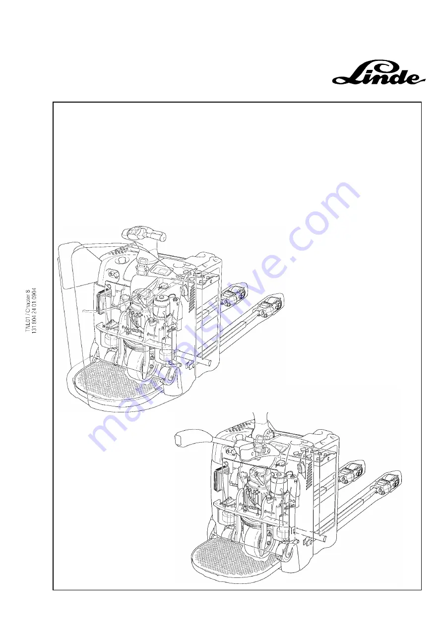
Page 118: ...TNL01 Chapter 8 131 804 24 01 0904 https www besttruckmanuals com...

Page 119: ...TNL01 Chapter 8 131 804 24 01 0 904 Electrical diagram Control T20 24 SP LAC https www besttruckmanuals com...

Page 120: ...TNL01 Chapter 8 131 804 24 01 0904 https www besttruckmanuals com...

Page 121: ...https www besttruckmanuals com...

Page 122: ...https www besttruckmanuals com...

Page 123: ...TNL01 Chapter 8 131 804 24 01 0 904 Electrical diagram Control T20 24 SP and AP LES https www besttruckmanuals com...

Page 124: ...TNL01 Chapter 8 131 804 24 01 0904 https www besttruckmanuals com...

Page 125: ...https www besttruckmanuals com...

Page 126: ...https www besttruckmanuals com...

Page 127: ...https www besttruckmanuals com...

Page 128: ...https www besttruckmanuals com...

Page 129: ...https www besttruckmanuals com...

Page 130: ...https www besttruckmanuals com...

Page 131: ...https www besttruckmanuals com...

Page 132: ...https www besttruckmanuals com...

Page 133: ...https www besttruckmanuals com...

Page 134: ...https www besttruckmanuals com...

Reviews: