background image

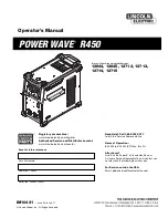
Operator’s Manual

POWER WAVE

®

R450

Register your machine:  

www.lincolnelectric.com/register

Authorized Service and Distributor Locator:  

www.lincolnelectric.com/locator

IM10421

|   Issue D ate July-17

© Lincoln Global, Inc.  All Rights Reserved.

For use with machines having Code Numbers:

12644, 12645, 12712, 12713,
12714, 12715

Need Help? Call 1.888.935.3877 

to talk to a Service Representative

Hours of Operation: 

8:00 AM to 6:00 PM (ET) Mon. thru Fri.

After hours? 

Use “Ask the Experts” at lincolnelectric.com
A Lincoln Service Representative will contact you 
no later than the following business day.

For Service outside the USA: 

Email: [email protected]

Save for future reference  

Date Purchased

Code: (ex: 10859)

Serial: (ex: U1060512345)

Summary of Contents for POWER WAVE R450

Page 1: ... Code Numbers 12644 12645 12712 12713 12714 12715 Need Help Call 1 888 935 3877 to talk to a Service Representative Hours of Operation 8 00 AM to 6 00 PM ET Mon thru Fri After hours Use Ask the Experts at lincolnelectric com A Lincoln Service Representative will contact you no later than the following business day For Service outside the USA Email globalservice lincolnelectric com Save for future ...

Page 2: ...N A LARGE ROOM OR OUTDOORS natural ventilation may be adequate if you keep your head out of the fumes See below USE NATURAL DRAFTS or fans to keep the fumes away from your face If you develop unusual symptoms see your supervisor Perhaps the welding atmosphere and ventilation system should be checked WEAR CORRECT EYE EAR BODY PROTECTION PROTECT your eyes and face with welding helmet properly fitted...

Page 3: ...ers and devices in position and in good repair Keep hands hair clothing and tools away from V belts gears fans and all other moving parts when starting operating or repairing equipment 1 e In some cases it may be necessary to remove safety guards to perform required maintenance Remove guards only when necessary and replace them when the maintenance requiring their removal is complete Always use th...

Page 4: ...m to ANSI Z87 I standards 4 b Use suitable clothing made from durable flame resistant material to protect your skin and that of your helpers from the arc rays 4 c Protect other nearby personnel with suitable non flammable screening and or warn them not to watch the arc nor expose themselves to the arc rays or to hot spatter or metal FUMES AND GASES CAN BE DANGEROUS 5 a Welding may produce fumes an...

Page 5: ...ent passing through lifting chains crane cables or other alternate circuits This can create fire hazards or overheat lifting chains or cables until they fail 6 h Also see item 1 c 6 I Read and follow NFPA 51B Standard for Fire Prevention During Welding Cutting and Other Hot Work available from NFPA 1 Batterymarch Park PO box 9101 Quincy MA 022690 9101 6 j Do not use a welding power source for pipe...

Page 6: ...ny other antenna or transmitter except in accordance with FCC multi transmitter product procedures Industry Canada IC 22017 LEWB0000111 This device complies with Industry Canada license exempt RSS standard s Operation is subject to the following two conditions 1 This device may not cause interference and 2 This device must accept any interference including inter ference that may cause undesired op...

Page 7: ...nt used for calibration or measurement g the immunity of other equipment in the environment The user shall ensure that other equipment being used in the environment is compatible This may require additional protection measures h the time of day that welding or other activities are to be carried out The size of the surrounding area to be considered will depend on the structure of the building and o...

Page 8: ...MENT B 2 PROCESS LIMITATIONS B 2 EQUIPMENT LIMITATIONS B 2 CASE FRONT CONTROLS B 3 CASE BACK CONTROLS B 4 COMMON WELDING PROCEDURES B 5 DEFINITION OF WELDING MODES B 5 BASIC WELDING CONTROLS B 5 SMAW STICK WELDING B 6 GTAW TIG WELDING B 6 CONSTANT VOLTAGE WELDING B 6 PULSE WELDING B 6 DIGITAL DISPLAY B 8 NAVIGATING THE USER CONFIGURATION MENU B 8 CONFIGURING AN ADDITIONAL DISPLAY B 9 FRONT ETHERNE...

Page 9: ...60 460 3 50 60 575 3 50 60 Input Amperes 80 73 41 37 29 60 54 31 27 21 Idle Power 500 Watts Max fan on Power Factor Rated Output 95 Input Voltage 10 208 230 400 460 575 50 60 Hz includes 380V to 415V Idle power is less than 50 watts when in Hibernation mode4 1 Based on U S National electrical Code 2 Also called inverse time or thermal magnetic circuit breakers circuit breakers that have a delay in...

Page 10: ... 95 Input Voltage 10 230 400 460 575 50 60 Hz includes 380V to 415V Idle power is less than 50 watts when in Hibernation mode5 For voltages higher than 460V or applications outside the European union replace input cord with properly rated cable 1 Based on U S National electrical Code 2 Also called inverse time or thermal magnetic circuit breakers circuit breakers that have a delay in tripping acti...

Page 11: ... 460 3 50 60 575 3 50 60 Input Amperes 41 37 29 31 27 21 Idle Power 500 Watts Max fan on Power Factor Rated Output 95 Input Voltage 10 400 460 575 50 60 Hz includes 380V to 415V Idle power is less than 50 watts when in Hibernation mode4 1 Based on U S National electrical Code 2 Also called inverse time or thermal magnetic circuit breakers circuit breakers that have a delay in tripping action that ...

Page 12: ...Hardened 4 F to 104 F 20C to 40C STORAGE TEMPERATURE RANGE Environmentally Hardened 40 F to 185 F 40C to 85C PROCESS GMAW GMAW Pulse FCAW GTAW DC SMAW OUTPUT RANGE AMPERES 40 550A 5 550A OCV Uo Mean Peak 60V 73V 24V 36V 60V 63V WELDING PROCESS A 4 INSTALLATION POWER WAVE R450 IP23 155º F Insulation Class Weight does not include input cord PHYSICAL DIMENSIONS TECHNICAL SPECIFICATIONS ALL MODELS ...

Page 13: ...60 1 6mm thick which shall extend not less than 5 90 150mm beyond the equipment on all sides LIFtIng Both handles should be used when lifting POWER WAVE R450 When using a crane or overhead device a lifting strap should be connected to both handles Do not attempt to lift the POWER WAVE R450 with accessories attached to it staCkIng The POWER WAVE R450 cannot be stacked tILtIng Place the machine dire...

Page 14: ...d type of the copper wires Fuse the input circuit with the recommended super lag fuse or delay type breakers also called inverse time or thermal magnetic circuit breakers Choose input and grounding wire size according to local or national electrical codes Using input wire sizes fuses or circuit breakers smaller than recommended may result in nuisance shut offs from welder inrush currents even if t...

Page 15: ...THREE PHASE CONDUCTOR HERE GROUND CONNECTION CONNECT GROUND LEAD PER LOCAL AND NATIONAL ELECTRIC CODE ROUTE INPUT CORD THROUGH RELIEF AND TWIST NUT TO TIGHTEN INPUT POWER ACCESS DOOR FIGURE A 1 for K3451 1 K3451 2 K3456 1 CONNECT EACH PHASE OF A THREE PHASE CONDUCTOR HERE INPUT POWER ACCESS DOOR INPUT CORD STRAIN RELIEF CE FILTER GROUND CONNECTION CONNECT GROUND LEAD PER LOCAL AND NATIONAL ELECTRI...

Page 16: ...ire feeder is recommended for Mig weld ing Refer to Figure A 3 for the connection details FIGURE A 3 Avoid excessive lengths and do not coil excess cable Ethernet Control Cable Remote Sense Lead Work Cable Work Piece Electrode Cable Water Feeder Dress Out Kit Flowmeter Torch ...

Page 17: ...ding performance Always use the largest welding cables electrode and work that are practical and be sure all connections are clean and tight Note Excessive heat in the weld circuit indicates undersized cables and or bad connections Route all cables directly to the work and wire feeder avoid excessive lengths and do not coil excess cable Route the electrode and work cables in close proximity to one...

Page 18: ... are connected With this feature there are no requirements for setting up the machine to use remote sense leads This feature can be disabled through the Weld Manager Utility available at www powerwavesoftware com or through the set up menu if a user interface is installed into the power source If the auto sense lead feature is disabled and remote voltage sensing is enabled but the sense leads are ...

Page 19: ...he remote WORK sense lead 21 can be accessed through the four pin voltage sense connector located on the control panel by using the K940 Sense Lead Kit It must be attached to the work as close to the weld as practical but out of the weld current path For more information regarding the placement of remote work voltage sense leads see in this section entitled Voltage Sensing Considerations for Multi...

Page 20: ...eads ARE Used Position the sense leads out of the path of the weld current Especially any current paths common to adjacent arcs Current from adjacent arcs can induce voltage into each others current paths that can be misinterpreted by the power sources and result in arc interference For longitudinal applications connect all work leads at one end of the weldment and all of the work voltage sense le...

Page 21: ...nnect all work leads on one side of the weld joint and all of the work voltage sense leads on the opposite side such that they are out of the current path See Figure A 7 POWER SOURCE 2 POWER SOURCE 1 POWER POWER SOURCE SOURCE 1 POWER SOURCE 2 2 POWER SOURCE 1 FIGURE A 7 ...

Page 22: ...s the power source to the wire feeder The control cable consists of two power leads one twisted pair for digital communication and one lead for voltage sensing The 5 pin ArcLink connection on the Power Wave R450 is located on the rear panel See Case Back Controls in the Operation Section The control cable is keyed and polarized to prevent improper connection Best results will be obtained when cont...

Page 23: ...combustibles ARC RAYS can burn Wear eye ear and body protection Observe additional guidelines detailed in the beginning of this manual POWEr uP sEQuEnCE When the POWER WAVE R450 is powered up it can take as long as 30 seconds for the machine to be ready to weld During this time period the user interface will not be active duty CyCLE The duty cycle is based on a ten minute period A 40 duty cycle re...

Page 24: ...R450 is recommended for robotic and semiautomatic welding The Power Wave R450 can be set up in a number of configurations some requiring optional equipment or welding programs Recommended Processes The POWER WAVE R450 is a high speed multi process power source capable of regulating the current voltage or power of the welding arc With an output range of 5 to 550 amperes it supports a number of stan...

Page 25: ...or the Service Manual for this machine See Troubleshooting Section for operational functions NOTE The Power Wave R450 status light will flash green and sometimes red and green for up to one minute when the machine is first turned on This is a normal situation as the machine goes through a self test at power up 4 Power Switch Controls power to the POWER WAVE R450 5 NEGATIVE WELD OUTPUT 6 POSITIVE W...

Page 26: ...uter or network connection 8 External I O CONNECTOR Terminal Strip for making simple input signal connections See Figure B 2A The terminal strip is divided into three groups Group 1 TRIGGER Group 2 FEED FORWARD REVERSE Group 3 SHUTDOWN INPUTS All inputs use normally open logic except the shutdown group The shutdown inputs use normally closed logic and are always enabled Unused shutdowns must be ti...

Page 27: ...elding mode offers the simplicity of single knob control The machine will select the correct voltage and amperage based on the Wire Feed Speed WFS set by the operator BasIC WELdIng COntrOLs Weld Mode Selecting a weld mode determines the output characteristics of the Power Wave power source Weld modes are developed with a specific electrode material electrode size and shielding gas For a more compl...

Page 28: ...E WELdIng Synergic CV For each wire feed speed a corresponding voltage is prepro grammed into the machine through special software at the factory The nominal preprogrammed voltage is the best average voltage for a given wire feed speed but may be adjusted to preference When the wire feed speed changes the POWER WAVE R450 automatically adjusts the voltage level correspondingly to maintain similar a...

Page 29: ... 50 to 1 25 At very low or high wire feed speeds the adaptive range may be less due to reaching physical limitations of the welding process UltimArc Control adjusts the focus or shape of the arc UltimArc Control is adjustable from 10 0 to 10 0 with a nominal setting of 0 0 Increasing the UltimArc Control increases the pulse frequency and background current while decreasing the peak current This re...

Page 30: ...ht Illuminates when voltage is displayed 9 Right DISPLAY window Displays voltage or units of alternative display naVIgatIng thE usEr COnFIguratIOn MEnu Simultaneously press the Left BUTTON and the Right BUTTON to enter the User Configuration menu Use the Selection KNOB to scroll through options the Right BUTTON to make a selection and the Left Button to return to the previous display The available...

Page 31: ...ts will change from joules J kilojoules kJ and megajoules MJ as appropriate Displaying Motor Current To display wire feeder motor current select MOTR CURR from the ALT DISP menu Every five seconds while welding the display will show motor current in amperes on the Left DISPLAY with AMPS on the Right DISPLAY Displaying WeldScore To display WeldScore select WELD SCOR from the ALT DISP menu Every fiv...

Page 32: ...er user manual available from www powerwavesoftware com Press the Right BUTTON to enter the WIRELESS menu then use the Selection KNOB to choose the desired option Press the Right BUTTON again to make a selection or the Left BUTTON to canvel the selection The following can be choosen WIFI ON OFF CONF Enable or disable Wi Fi or place the Wi Fi in configuration mode IP ADDR Display the Power Wave s W...

Page 33: ...identify it as a Bluetooth device select BT NAME The display will show the current Bluetooth name for the Power Wave This name can be used when pairing the Power Wave to a computer or other device with Bluetooth WI FI status IndICatOr LIght The green Wi Fi STATUS INDICATOR light indicates the connection type and uses the three bars to indicate the strength of the Wi Fi signal The meanings of the i...

Page 34: ...lincolnelectric com Welding Fume Extractors Lincoln offers a wide range of fume extraction environmental sys tem solutions ranging from portable systems easily wheeled around a shop to shop wide central systems servicing many dedi cated welding stations Request Lincoln publication E13 40 See www lincolnelectric com ...

Page 35: ...0 is critical to its operation Generally speaking the calibration will not need adjustment However neglected or improperly calibrated machines may not yield satisfactory weld performance To ensure optimal performance the calibration of output Voltage and Current should be checked yearly CaLIBratIOn sPECIFICatIOn Output Voltage and Current are calibrated at the factory Generally the machine calibra...

Page 36: ...oughout this manual This Troubleshooting Guide is provided to help you locate and repair possible machine malfunctions Simply follow the three step procedure listed below Step 1 LOCATE PROBLEM SYMPTOM Look under the column labeled PROBLEM SYMPTOMS This column describes possible symptoms that the machine may exhibit Find the listing that best describes the symptom that the machine is exhibiting Ste...

Page 37: ...ion Steady Green Blinking Green Fast Blinking Green Alternating Green and Red Steady Red Blinking Red Status LED off Meaning Main control board status light and Input control board System OK Power source is operational and is communicating normally with all healthy peripheral equipment connected to its ArcLink network Occurs during power up or a system reset and indicates the POWER WAVE R450 is ma...

Page 38: ...machine does not clear the error contact the Service Department Review error code from input board status light or status beeper Most likely caused by an over power condition which caused an under voltage on the prima ry bus If cycling the input power on the machine does not clear the error contact the Service Department The long term secondary Weld power limit has been exceeded NOTE The long term...

Page 39: ...dropped out Check connections and verify quality of input power Temporary 346 Transformer Primary Overcurrent Transformer current too high Typically indicates short term power overload If problem persists contact the Serivce Department Persistent 347 Average Input Current Limit Average input current limit has been exceeded Typically indicates short term power overload If problem persists contact S...

Page 40: ...on section of this manual for recommended sizes 2 Reduce output current duty cycle or both 3 Contact your local authorized Lincoln Electric Field Service facility for techni cal assistance 1 Make sure input supply disconnect has been turned ON Check input fuses Make certain that the Power Switch SW1 on the power source is in the ON position 2 Make certain that input voltage is cor rect according t...

Page 41: ...rs or for exces sive dirt clogging cooling channels in machine 2 Check for broken wires open connec tions or faulty thermostats in the ther mostat circuit 1 Replace the battery Type BS2032 1 Check for feeding problems 2 Check for bad connections excessive loops in cable etc NOTE The presence of heat in the exter nal welding circuit indicates poor connec tions or undersized cables 3 Verify gas flow...

Page 42: ...uce load to lower current draw from the machine 2 A non recoverable fault will interrupt welding This condition will also result in a status light blinking See the Status Light section for more information 1 Make certain that the input voltage is proper according to the Rating Plate located on the rear of the machine 2 Verify all 3 phases are present 3 Calibrate secondary current and voltage 1 Che...

Page 43: ... network device 2 Use the appropriate PC utility to verify the correct IP address information has been entered 2a Verify no duplicate IP addresses exist on the network 3 Verify that the network device connected to the Power Wave is either a 10 baseT device or a 10 100 baseT device 10 baseT is recommended 1 Verify Network cable is not located next to current carrying conductors This would include i...

Page 44: ... 1 3 5 4 8 1 2 1 6 6 12 1 J10A1 J10B1 J811 J2 J3 J4 J45 J61 J86 J2 J5 J11 J31 J46 J51 J111 J82 J81 J9 J13 J16 J26 J27 J62 J112 J83 J1 J8 J24 J28 J29 J43 J47 J63 J84 J12 J23 J25 J42 J6 J7 J41 J85 J87 INPUT SWITCH B3 B1 B2 L3 L1 L2 10 9 8 7 6 5 J1 POWER BOARD G6846 B2 BL6 BL5 BL4 BL3 BL2 BL1 OUTPUT CHOKE L13270 4 HEAT SINK 1 2 3 4 5 6 7 8 J41 342 343 344 345 346 347 348 341 336A 4 3 2 1 1 2 3 4 5 6 ...

Page 45: ... L13 L14 L15 L16 1047 MF 1047 MF 0141 MF 0141 MF L17 L20 L21 CAVITY NUMBERING SEQUENCE VIEWED FROM COMPONENT SIDE OF P C BOARD 6 5 10 1 3 4 1 2 9 8 16 1 4 6 1 3 5 4 8 1 2 1 6 6 12 1 J10A1 J10B1 J811 J2 J3 J4 J45 J61 J86 J2 J5 J11 J31 J46 J51 J111 J82 J81 J9 J13 J16 J26 J27 J62 J112 J83 J1 J8 J24 J28 J29 J43 J47 J63 J84 J12 J23 J25 J42 J6 J7 J41 J85 J87 INPUT SWITCH B3 B1 B2 L3 L1 L2 POWER BOARD G6...

Page 46: ...B3 B2 B1 B3 1047 MF 1047 MF 0141 MF 0141 MF L17 L8 CAVITY NUMBERING SEQUENCE VIEWED FROM COMPONENT SIDE OF P C BOARD 6 5 10 1 3 4 1 2 9 8 16 1 4 6 1 3 5 4 8 1 2 1 6 6 12 1 J10A1 J10B1 J811 J2 J3 J4 J45 J61 J86 J2 J5 J11 J31 J46 J51 J111 J82 J81 J9 J13 J16 J26 J27 J62 J112 J83 J1 J8 J24 J28 J29 J43 J47 J63 J84 J12 J23 J25 J42 J6 J7 J41 J85 J87 INPUT SWITCH B3 B1 B2 L1 L2 L3 T1 T2 T3 L3 L1 L2 POWER ...

Page 47: ...F 4 NOTES L16215 A 01 13 94 22 45 27 43 6 00 18 35 24 76 ...

Page 48: ...F 5 NOTES ...

Page 49: ......

Page 50: ...parts or electrode with skin or wet clothing l Insulate yourself from work and ground l No toque las partes o los electrodos bajo carga con la piel o ropa moja da l Aislese del trabajo y de la tierra l Ne laissez ni la peau ni des vête ments mouillés entrer en contact avec des pièces sous tension l Isolez vous du travail et de la terre l Berühren Sie keine stromführenden Teile oder Elektroden mit ...

Page 51: ... und Entlüftung des Arbeitsplatzes l Mantenha seu rosto da fumaça l Use ventilação e exhaustão para remover fumo da zona respiratória l Turn power off before servicing l Desconectar el cable de ali mentación de poder de la máquina antes de iniciar cualquier servicio l Débranchez le courant avant l entre tien l Strom vor Wartungsarbeiten abschalten Netzstrom völlig öff nen Maschine anhalten l Não o...

Page 52: ...stomer s particular purpose with respect to such information or advice As a matter of practical consideration we also cannot assume any respon sibility for updating or correcting any such information or advice once it has been given nor does the provision of information or advice create expand or alter any warranty with respect to the sale of our products Lincoln Electric is a responsive manufactu...

Reviews: