background image

METEOR, 

MAGNETIC UPRIGHT BIKE 

ITEM NO: 20590 


OWNER’S MANUAL


IMPORTANT: Read all instructions carefully before using this product.    Retain this 
owner’s manual for future reference. 

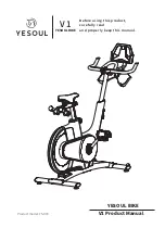
The specifications of this product may vary from this photo, subject to change without notice. 
                                                                                                                                                                       

2014, Dec.


Summary of Contents for METEOR

Page 1: ...20590 OWNER S MANUAL IMPORTANT Read all instructions carefully before using this product Retain this owner s manual for future reference The specifications of this product may vary from this photo subject to change without notice 2014 Dec ...

Page 2: ... 2 IMPORTANT SAFETY INSTRUCTIONS 3 PARTS LIST 4 HARDWARE PACKING LIST 5 TOOLS 5 OVERVIEW DRAWING 6 ASSEMBLY INSTRUCTIONS 7 OPERATING THE COMPUTER 12 ADJUSTMENTS 14 MAINTENANCE 15 TROUBLESHOOTING 15 WARM UP AND COOL DOWN ROUTINE 16 ...

Page 3: ...r repairing free of charge any parts which may prove to be defective under normal home use This warranty does not include any damage caused by improper operation misuse or commercial application From the date of purchase the frame is warranted to be free from defects for 1 one year This warranty is offered only to the original owner and is not transferable Proof of purchase is required When orderi...

Page 4: ...maintenance or adjustments other than those described in this manual Should any problems arise discontinue use and consult your local dealer 6 Do not use the equipment outdoors 7 This equipment is for household use only 8 Only one person at a time should use this equipment 9 If you feel any chest pains nausea dizziness or short of breath you should stop exercising immediately and consult your phys...

Page 5: ...dlebar Foam Grip Ø24xØ30x490 2 014 Curve Washer Ø8xØ20x1 5t 4 044 Left Foot Pedal YH 30X 1 015 Seat Adjustment Knob M10 1 045 Right Foot Pedal YH 30X 1 016 Spring Washer Ø6 2 046 Handlebar End Cap Ø25 2 017 Carriage Bolt M8x70 2 047 Cover Cap Ø40xØ25x10 2 018 Square End Cap 38 2 048 Seat Post Knob M16x1 5 1 019 Bolt M8x15 2 049 Hand Pulse Sensor with Wire L 750mm 2 020 Bolt M8x30 1 050 Sensor with...

Page 6: ...64 Handlebar T Knob M8x55 1 072 Rear Right Stabilizer End Cap Ø60 1 065 Washer Ø12xØ6x1t 1 073 Hexagon Nut M10x6t 2 066 Bolt M6x10 1 074 Adjustable Leveler M10 2 067 Wire Grommet Ø12 1 1 075 Bolt M8x70 2 068 Seat Sliding Tube Bolt 1 076 Washer Ø14xØ10xδ1 0 2 Multi Hex Tool 1 PC Multi Hex Tool with Phillips Screwdriver 1 PC Allen Wrench S6 1 PC 14 Curve Washer Ø8xØ20x1 5t 4 PCS 17 Carriage Bolt M8x...

Page 7: ...6 47 26 12 2 13 58 53 50 59 5 15 69 18 68 27 61 54 64 55 7 57 56 62 52 60 45 39 44 36 34 33 32 48 1 72 73 74 73 74 71 43 8 43 49 46 24 24 28 16 9 28 16 9 17 24 14 30 41 40 21 66 22 4 18 25 25 26 47 26 42 67 10 70 19 10 75 3 6 65 63 20 70 11 49 70 29 14 76 ...

Page 8: ... Stabilizer 3 Foot Pedals Installation The Cranks Foot Pedals Pedal Shafts and Pedal Straps are marked R for Right and L for Left Insert the pedal shaft of Left Foot Pedal 44 into threaded hole in the left Crank 39 Turn the pedal shaft by hand in the counter clockwise direction until snug Note DO NOT turn the pedal shaft in the clockwise direction doing so will strip the threads Tighten the pedal ...

Page 9: ... three Ø8xØ16x1 5t Washers 10 from underside of the Seat Cushion 61 Remove nylon nuts with the Multi Hex Tool with Phillips Screwdriver provided Guide bolts on underside of the Seat Cushion 61 through holes on top of the Seat Sliding Tube 6 attach with three removed M8 Nylon Nuts 27 and Ø8xØ16x1 5t Washers 10 Tighten nylon nuts with the Multi Hex Tool with Phillips Screwdriver provided Guide the S...

Page 10: ...ere removed Tighten bolts with the S6 Allen Wrench provided Slide the Handlebar Post Cover 58 down to the Handlebar Post 7 Remove the M5x20 Bolt 40 and Ø5xØ15x1 0t Washer 41 from the Tension Control Knob 54 Remove bolt with the Multi Hex Tool with Phillips Screwdriver provided Put the cable end of resistance cable of Tension Control Knob 54 into the spring hook of Tension Cable 55 see Figure A Pul...

Page 11: ...bar Post 7 Place the Handlebar 8 through clamp on the Handlebar Post 7 with hand pulse sensors facing the seat Hold the Handlebar 8 in desired position and fasten Clamp Cover 56 Ø12x20 Spacer 57 and Handlebar T Knob 64 onto clamp Tighten the Handlebar T Knob 64 after adjustment NOTE Handlebar T Knob should be tightly secured before using 56 57 64 8 7 49 ...

Page 12: ...e Sensor Wires 49 and Extension Sensor Wire 63 to the wires that come from the Computer 62 Tuck wires into the Handlebar Post 7 Attach the Computer 62 onto the top end of the Handlebar Post 7 with four M5x10 Bolts 42 that were removed Tighten bolts with the Multi Hex Tool with Phillips Screwdriver provided 42 62 63 49 7 8 Tool Multi Hex Tool with Phillips Screwdriver ...

Page 13: ...ORIES or PULSE to zero for target pre setting Press and hold the RESET button for 3 seconds to reset all data values to zero except the ODO ODOMETER data values COMPUTER FUNCTIONS SCAN Press the MODE button until the screen displays SCAN the computer will automatically scan each function in sequence with change every 6 seconds TIME Displays your elapsed workout time in minutes and seconds You may ...

Page 14: ...ll begin beeping to remind you This data is a rough guide for comparison of different exercise sessions and should not be used in medical treatment ODO ODOMETER Displays the total accumulative distance traveled The data values of ODO can not be clear to zero by pressing and holding the MODE or RESET button for 3 seconds If you take out the batteries from the computer the ODO data values will clear...

Page 15: ...ection until it can be pulled out Pull out the seat post knob and then slide the seat post up or down direction to the suitable position Lock the seat post in place by releasing the seat post knob and sliding the seat post up or down slightly until the seat post knob pops down into the locked position For added safety tighten the seat post knob in a clockwise direction NOTE When adjusting the heig...

Page 16: ...o display on the computer console 1 Remove the computer console and verify the wires that come from the computer console are properly connected to the wires that come from the handlebar post 2 Check if the batteries are correctly positioned and battery springs are in proper contact with batteries 3 The batteries in the computer console may be dead Change to new batteries There is no heart rate rea...

Page 17: ... state at the end of each exercise session A proper cool down slowly lowers your heart rate and allows blood to return to the heart HEAD ROLLS Rotate your head to the right for one count you should feel a stretching sensation up the left side of your neck Then rotate your head back for one count stretching your chin to the ceiling and letting your mouth open Rotate your head to the left for one co...

Page 18: ...Lean against a wall with your left leg in front of the right and your arms forward Keep your right leg straight and the left foot on the floor then bend the left leg and lean forward by moving your hips toward the wall Hold then repeat on the other side for 15 counts TOE TOUCHES Slowly bend forward from your waist letting your back and shoulders relax as you stretch toward your toes Reach as far a...

Reviews: