LG V-CB564ST, Service Manual
The LG V-CB564ST Service Manual is available for free download on our website. This comprehensive manual provides detailed instructions and technical information to help users effectively troubleshoot and repair their LG V-CB564ST. Experience hassle-free maintenance and obtain the manual directly from manualshive.com today.
Share
Download


Reviews:
No comments
Related manuals for V-CB564ST
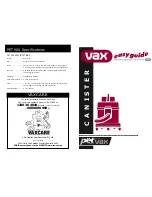
CANISTER
Brand: Vax Pages: 6

SC1Z1
Brand: MONSTER FLOOR Pages: 16

Ultima Cyclonic VZL-101
Brand: Vax Pages: 12

KP701
Brand: kincrome Pages: 9

AP-1008BH
Brand: Coway Pages: 24

RHHS3001
Brand: Russell Hobbs Pages: 20

TURBINE POWERHEAD and HAND HELD TURBINE...
Brand: H-P Products Pages: 10

Protector L
Brand: Roller Pages: 56

Solaris SlXLED
Brand: Ultravation Pages: 2

DEEBOT OZMO 610
Brand: ECOVACS ROBOTICS Pages: 6

SM102B
Brand: Euroclean Pages: 52

R-1650C
Brand: Rainbow Pages: 8

VB1600
Brand: Black & Decker Pages: 68

T8
Brand: Electrolux Pages: 20

Rapido ZB4112
Brand: Electrolux Pages: 12

Rapido ZB5104WDB
Brand: Electrolux Pages: 10

RAPIDO WET AND DRY
Brand: Electrolux Pages: 13

Rapido ZB4103
Brand: Electrolux Pages: 60


