LG 47LX9500, Service Manual
Looking for the LG 47LX9500 Owner's Manual? You can now download it for free from manualshive.com. This comprehensive manual provides detailed instructions on setting up and operating your LG 47LX9500, helping you make the most of this exceptional product.
Share
Download


Reviews:
No comments
Related manuals for 47LX9500

BN68-02714F-02
Brand: Samsung Pages: 2

CL-21M21MQ
Brand: Samsung Pages: 63

CL-17K10MJ
Brand: Samsung Pages: 63

FP-T5094W
Brand: Samsung Pages: 2

SANVITO 10.1 WM V2.1
Brand: Garz Fricke Pages: 25

MXT-701
Brand: AMX Pages: 2

50RESI
Brand: NEC Pages: 36

107FP4
Brand: Philips Pages: 2

NSX-24GT1 (PDF)
Brand: Sony Pages: 2

LCD TV XBR-52LX900
Brand: Sony Pages: 2

KV-36HS420 - 36" Fd Trinitron Wega
Brand: Sony Pages: 1

KE-P42MRX1
Brand: Sony Pages: 2
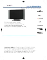
KE-42XS910 - 42" Flat Panel Color Tv
Brand: Sony Pages: 2

KE-42XBR900 - 42" Xbr Plasma Wega™ Integrated Television
Brand: Sony Pages: 2

KE-42TS2 - 42" Flat Panel Color Tv
Brand: Sony Pages: 1

NSX-24GT1 (PDF)
Brand: Sony Pages: 40

KZ-32TS1U
Brand: Sony Pages: 73

KE-MR50M1 CH
Brand: Sony Pages: 68


