Leuze electronic rotoScan ROD4 plus Series, Original Operating Instructions
The Leuze electronic rotoScan ROD4 plus Series, a cutting-edge sensor solution, offers unparalleled performance and reliability. Make the most of this innovative product by accessing the Original Operating Instructions manual for free download at manualshive.com. Equip yourself with essential knowledge to fully utilize the product's features and functionalities.
Share
Download


Reviews:
No comments
Related manuals for rotoScan ROD4 plus Series

Duplex
Brand: Xerox Pages: 62

FS-450M TWIN
Brand: J.P. Instruments Pages: 28

P3PC-7032-01XA
Brand: ScanSnap Pages: 5

PF1800Lab
Brand: Pacific Image Electronics Pages: 19

XD2490
Brand: Contex Pages: 57

PKT 4000
Brand: PrehKeyTec Pages: 21

EC9600i series
Brand: RDM Pages: 2

ImageFormula R10
Brand: Canon Pages: 7

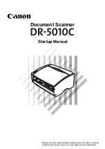
9080C - DR - Document Scanner
Brand: Canon Pages: 16

500F - CanoScan LiDE
Brand: Canon Pages: 22

3950B002
Brand: Canon Pages: 2

CanoScan 2700F
Brand: Canon Pages: 60

CanoScan 9000F
Brand: Canon Pages: 39
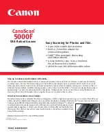
5000F - CanoScan Scanner
Brand: Canon Pages: 2

Canoscan 8800
Brand: Canon Pages: 6
CanoScan FS2720U
Brand: Canon Pages: 30
9842A002
Brand: Canon Pages: 96

CanoScan 8000F
Brand: Canon Pages: 19


