Page 1 of 13
LANDING GEAR
Part No. H00550
Height Adjustable Load Bearing Support for Lets Go Aero Cargo Carriers
7/16in Socket and Wrench
9/16in Socket & Wrench
A
B
C
D
E
F
G
H
J
K
L
M
N
P
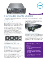
4
4
1
1
1
4
4
4
8
8
8
19
19
3
LEG
CHANNEL
LONG SUPPORT BAR (25.6IN)
RIGHT SUPPORT BAR (22.5IN)
LEFT SUPPORT BAR (22.5IN)
NYLON SPACERS
3/8” X 1” BOLT (LG)
3/8” X 3/4” BOLT (MD)
3/8” WASHER (LG)
3/8 NUT NYLOCK (LG)
U-BOLT
1/4” NYLOCK NUT (SM)
1/4” WASHER (SM)
1/4-20 X 3/4 BOLTS (SM)
PARTS LIST
QTY. DESCRIPTION
A
B
C
D
E
F
G
H
J
K
L
M
N
P
Landing Gear is a universal accessory option designed for select Let’s Go Aero Slide Out Cargo Carrier models:
GearSpace™ (HGK819 & HGK826), GearDeck™ (H00604), GearCage® FP-6 (H01397), GearCage® FP-4 (H01830),
BigBox™, BlackBox™, & other Mobility Carrier Models in the GearCage Products Family.
TABLE OF CONTENTS:
GEARSPACE & GEARDECK ASSEMBLY
GEARCAGE, BLACK BOX, BIGBOX, & MOOVER ASSEMBLY
LANDING GEAR OPERATION
WARRANTY & SAFE USE NOTICE
2
7
11
13
..........................................................................
.........................................
.............................................................................................
.....................................................................................
SECTION:
PAGE NUMBER:
LG MANUAL 032918
GENERIC INSTALLATION SHOWN FOR CLARITY
Tools Needed
WATCH THE ASSEMBLY VIDEO
YOUTUBE.COM/LETSGOAEROTV
Depending on your carrier, some hardware will not be used and may be discarded once installation is complete.
DO NOT EXCEED LOAD
WEIGHT LIMIT OF 250LBS
WARNING: