NOTE: Do not print Pantone Red 032,
it is for print registration only.
Front
!
Flex
Enterpise
System
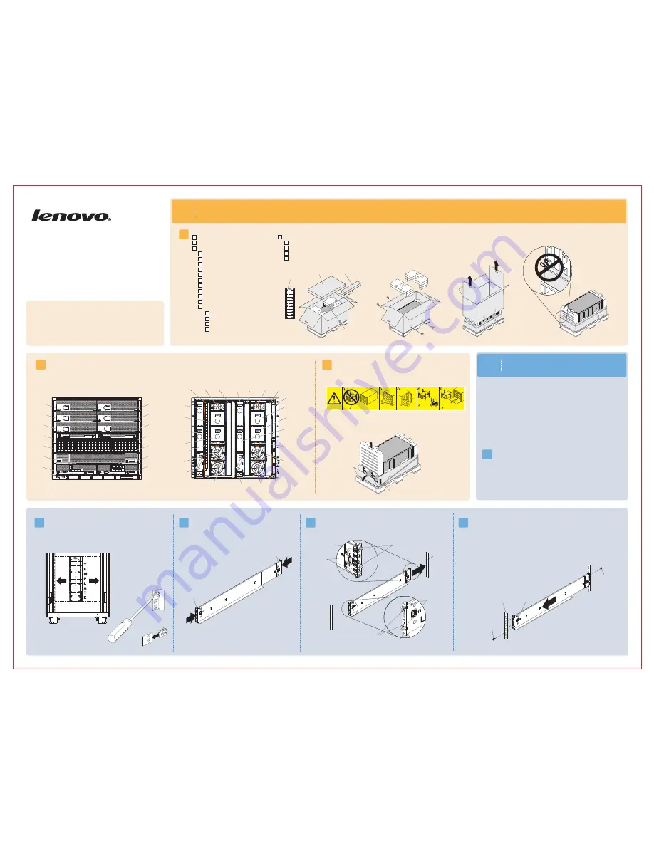
1
Before you begin
1.1
Lenovo Flex System
Enterprise Chassis
Types 7893, 8721,
and 8724
Quick Start Instructions
Before you install this product, read the safety information in the
Lenovo
System Enterprise Chassis
Types 7893, 8721, and 8724
Installation and
Service Guide
.
Flex
2.2
2.4
2.3
Note:
1. Make sure that the bottom edge of the chassis rail is aligned with the bottom U that
you want the chassis to rest on.
2. If you misalign the chassis rail, press the locking hooks release or squeeze the locking hooks
on the chassis rail, slide the posts out of the holes, and try again.
3. Make sure that the chassis rail posts protrude through the holes
on the front EIA flange.
Note:
For detailed instructions, see the
Lenovo Flex System Enterprise Chassis
Types 7893, 8721, and 8724 Installation and Service Guide.
2.5
Pull the chassis rail forward and insert the posts on the front of the chassis rail into the
holes on the front EIA flange until it snaps into place. Repeat steps 2.4 and
2.5 for the right chassis rail.
Verify the shipment contents:
1.2
Become familiar with the chassis components. The following modules are standard:
One
System Chassis Management Module (CMM), two or more power supplies, six or more fan modules, and two fan logic modules. The chassis might
also include one or more compute nodes, storage nodes, and a management node. The features or modules that you receive might differ from the contents
shown in Figures 1 and 2, depending on what you ordered (see Figures 1 and 2).
Flex
Learn more about the Lenovo Flex System Enterprise Chassis through the
learning modules at
http://pic.dhe.ibm.com/infocenter/flexsys/information/index.jsp.
This site also contains the Flex System product documentation.
Position the left chassis rail in the selected location on the rear of the rack.
Align the posts on the chassis rail with the corresponding holes on the rear EIA
flange. Insert the posts on the rear of the chassis rail through the holes on
the rear EIA flange until the hooks snap into place.
Rear EIA
flange
1.3
66.2 kg
(146 lbs)
220.4 kg (468 lbs)
44.90 kg (99 lbs)
(14X)
(7X)
(6X)
(4X)
(10X)
or
I/O
To decrease the weight and make the chassis easier to install in a rack, remove
components from the chassis. Make a note of each component location so that
the component can be reinstalled in the same location. Press on the colored
latch and pull on the handles to remove the components. You can also remove
the shelves from the chassis to reduce the weight further.
4. Install an M5 combi-head screw in each end of the rail.
Use the lower threaded hole on the front and the upper
threaded hole on the rear.
Figure 2. Rear view of the Lenovo Flex System Enterprise Chassis
Power-
supply
bay 6
Power-
supply
bay 5
Power-
supply
bay 4
Fan
bay 10
Fan
bay 9
Fan
bay 8
Fan
bay 7
Fan
bay 6
Fan logic
bay 2
I/O bay 1
Power-supply
bay 1
I/O bay 3
Power-
supply
bay 3
I/O bay 2
Fan
bay 5
I/O bay 4
CMM
bay 2
Power-
supply
bay 2
Fan
bay 4
Fan
bay 3
Fan logic
bay 1
Fan
bay 2
Fan
bay 1
CMM
bay 1
M5 clip nut
Front of rail
Rear of rail
Locking
hooks
release
LEFT FR
ONT
Front EIA
flange
LEFT FR
ONT
Retract both chassis rails, if they are not already retracted.
LEFT FR
ONT
Figure 1. Front view of the Lenovo
System Enterprise Chassis
Flex
Bay 1
Bay 5
Bay 3
Bay 7
Bay 11
Bay 9
Bay 13
Bay 2
Bay 6
Bay 4
Bay 8
Bay 12
Bay 10
Bay 14
Information
panel
To access the lower chassis components, loosen the Sanstrap stretch band
on the bottom tray and fold the bottom tray flaps down.
M5 combi-head
screw (black)
Posts
Hooks
Threaded hole
Hooks
Posts
Threaded hole
Note:
Do not cut the Sanstrap stretch band on the bottom tray.
10 M5 x 16 combi-head screws (black)
8 M5 x 16 captive-washer screws (silver)
12 M5 clip nuts - 74F1823
12 M5 cage nuts - 81Y2820
1 lower shipping bracket - 81Y2988
1 left shipping bracket - 81Y2986
1 right shipping bracket - 81Y2991
4 chassis lift handles
1 power cable per power supply
1 Sanstrap stretch band
Accessory kit
Rack installation
template
10 hook-and-loop strips - 51H9502
8 M5 x 16
1 left chassis-mounting rail
1 right chassis-mounting rail
combi-head screws (4 extra, black)
Rail installation kit - 88Y6763
Accessory kit
Rail installation kit
Flex System chassis
Sanstrap stretch band
M5 cage nut
2
Install the Lenovo
Enterprise Chassis in a rack
Flex System
• You will need at least 10U of available space to install the Lenovo Flex
System Enterprise Chassis.
2.1
Remove the rack door, if one is installed on the rack.
M5 combi-head
screw (black)
Lenovo Flex System Enterprise Chassis
Rack installation template
Enterprise Chassis Documentation CD
Important Notices
document
Statement of Limited Warranty
ode labels
N
Documentation kit
Align the rack template with the holes in the EIA flange (internal to rack).
For EIA flanges with square holes, install M5 cage nuts from the accessory
kit in the holes that are indicated on the template. If the EIA flanges have
round holes, install the M5 clip nuts from the accessory kit instead of the
M5 cage nuts.
Note:
Install cage nuts or clip nuts on the front and back EIA flanges.
• Make sure that there is sufficient room in front of the front EIA flange to
provide minimum bezel clearance of 50 mm (1.97 inches).
•
EIA flanges to 719 mm (28.3 inches) outside to outside.
If you have an adjustable rack, set the distance between the front and rear