Lennox ComfortSense 7500, Installation And Setup Manual
The Lennox ComfortSense 7500 is a state-of-the-art thermostat that allows you to have complete control over your home's temperature. To fully harness its potential, it is crucial to have the user manual at hand. Download the comprehensive user manual for free from our website for a seamless experience.
Share
Download


Reviews:
No comments
Related manuals for ComfortSense 7500
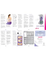
Elle TENS
Brand: Babycare TENS Pages: 2

HH506RA
Brand: Omega Pages: 3

A3918
Brand: Beijing Pages: 2

HI 98710
Brand: Hanna Instruments Pages: 15

EMR812HGN
Brand: Oregon Scientific Pages: 12

THAT040E
Brand: Thermofilm Pages: 2

TP-P-625
Brand: Vive Comfort Pages: 8

TP-N-631
Brand: Vive Comfort Pages: 4

8045
Brand: ritetemp Pages: 5

8082
Brand: ritetemp Pages: 8

8022
Brand: ritetemp Pages: 9

8050C
Brand: ritetemp Pages: 10

MCA-900II
Brand: BONKOTE Pages: 8

KD-2220
Brand: CVS Pharmacy Pages: 13

ULTRA
Brand: Traceable Pages: 4

TOTALINE GOLD P274-0150
Brand: Carrier Pages: 4

TST-EEPC06111SCS00
Brand: Carrier Pages: 12

TC-PHP01-BLK
Brand: Carrier Pages: 36


