Leica DMI6000 B, Operating Manual
The Leica DMI6000 B is a high-quality microscope designed for advanced research and imaging applications. For detailed instructions on how to operate this sophisticated instrument, download the Operating Manual for free from our website. Ensure optimal performance and maximize the capabilities of your Leica DMI6000 B with this essential manual.
Share
Download


Reviews:
No comments
Related manuals for DMI6000 B

Lx 400
Brand: Labomed Pages: 32

G-series
Brand: X-Loupe Pages: 18
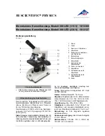
300 LED 1013366
Brand: 3B SCIENTIFIC PHYSICS Pages: 12

?IGMA VP-FE-SEM
Brand: Zeiss Pages: 22

Alphaphot
Brand: Nikon Pages: 15

A1
Brand: Nikon Pages: 88

1200CM Series
Brand: Van Guard Pages: 20

Stemi 508
Brand: Zeiss Pages: 326

EXS-210-24
Brand: Accu-Scope Pages: 13

MF52-N
Brand: MshOt Pages: 19

eclipse lv150
Brand: Nikon Pages: 75

EDU-41011
Brand: Elenco Electronics Pages: 2

EDU-41002
Brand: Elenco Electronics Pages: 2

EDU-4004
Brand: Elenco Electronics Pages: 2

85908
Brand: Betzold Pages: 22

630-2648
Brand: VWR Pages: 60

BioDiscover
Brand: Bresser Pages: 20

ERUDIT Basic
Brand: Bresser Pages: 8


