Leica Geosystems GPS500, General Manual
The Leica Geosystems GPS500 user manual is a comprehensive General Manual that is available for free download on our website. This manual provides detailed instructions and helpful information on operating the GPS500, ensuring users can optimize its performance and accuracy. Download your free copy from manualshive.com.
Share
Download


Reviews:
No comments
Related manuals for GPS500
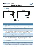
Zeus2 series
Brand: B&G Pages: 8

Zeus3S
Brand: B&G Pages: 51
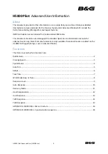
H5000 Pilot
Brand: B&G Pages: 18

Zeus3S
Brand: B&G Pages: 140

76CS GPS
Brand: Garmin Pages: 4

VT401
Brand: Mongoose Pages: 16

M-DVD6000DAB
Brand: Macrom Pages: 32

PET FINDER
Brand: PAJ GPS Pages: 64
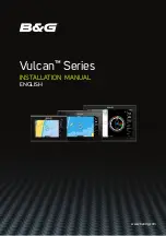
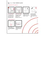
Vulcan Series
Brand: B&G Pages: 68

CVUK-TR32
Brand: Chinavision Pages: 14
TU50X-1 SPOT
Brand: Trackunit Pages: 4

Horizon
Brand: CompeGPS Pages: 2

EVA1084
Brand: Maestro Pages: 18

GA-4640
Brand: G Sat Pages: 23

SkyStar
Brand: XAiOX Pages: 17

UM666
Brand: UniGuard Pages: 6

Compasseo 800
Brand: Packard Bell Pages: 10

Apollo GX 50
Brand: II Morrow Inc. Pages: 38


