

Assign IP
Caution:
The IP address you assign must be within
a valid range, be unique to your network, and be
in the same subnet as your PC.
Note:
For the convenience of assigning an IP address
over your Ethernet network, refer to the “Using ARP
and Ping” section of the Installation Guide.
1) Connect a null modem cable between your computer
and the unit’s console port (#1).
2) Open a terminal emulator (e.g., Hyperterminal).
3) Confirm that the configuration parameters are set
as follows:
9600 Baud, 8/N/1, Xon/Xoff flow control
.
4) Press the Enter key.
5) Enter any user name.
6) At the local prompt enter:
set privileged
7) Enter
system
for the password.
8) At the local prompt enter:
change server ipadd [xxx.x.x.xx.]
Configure
1) Open a Web browser.
2) Enter the
IP address
you just assigned into the URL
address field.
3) Confirm that the following screen displays:
4) Click on the
Port Properties
heading.
The MSS4 network-enables Industrial Automation,
Medical Instruments, modems, and other serial devices.
Each of its four ports can accommodate RS232, RS422, or
RS485 communication.
The MSS4 delivers remote management and data accessi-
bility through its 10/100BASE-T Ethernet port or its
optional 100BASE-FX fiber link port. Its two optional PC
card slots provide flash storage or wireless Ethernet.
This Quick Start explains how to connect, configure, and
troubleshoot your unit. For more detailed information,
refer to the MSS Installation Guide and Reference Manual
on the CD ROM supplied with this product.
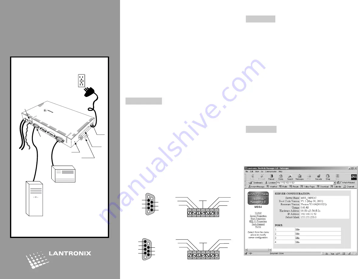
Connections
1) Place the MSS4 near your serial devices
2) Connect your Ethernet cable to the unit’s RJ45
Ethernet port.
3) Optionally, connect your full duplex fiber optic Ethernet
cables to the unit’s ST connectors.
Note:
If you wish to use the optional Power Terminal
Block, refer to the Installation Guide.
4) Connect power (9 to 30 VDC, 3W maximum).
5) Wait about 30 seconds.
6) Confirm that the
Link
LED lights up.
7) Confirm that the
OK
LED is slowly blinking.
8) Note the pin assignments of the terminal blocks
and DB9 connectors:
Power, Serial, Ethernet Connections
MSS4
Quick Start
MSS4
MSS4
serial 4
serial 3
serial 2
serial 1
pc car
d 1
pc car
d 2
link
ok
10/100
100 BaseFX
TX RX
se
rial 1
2
3
4
reset
pc car
d
1
2
9-30vdc
Ethernet
Optional
Fiber
Computer
Serial Device
Reset
Button
Mounting
Bracket
Optional
PC Card
Slots (2)
Power
Terminal
Block
RJ45
Jack
Console
Port
5
1
9
6
RX
TX
DTR
CTS
RTS
DSR
Grd.
1
5
6
9
NC
TX+
RX+
NC
TX-
RX-
7 1
DSR
CTS
RX
Grd.
TX
RTS
DTR
7 1
NC
RX-
RX
÷
Grd.
TX
÷
TX-
NC
RS-485
RS-232