background image

                                                                                   F-607-0818

LANDOLL CORPORATION

1900 North Street

Marysville, Kansas 66508

(785) 562-5381

800-428-5655 ~ WWW.LANDOLL.COM
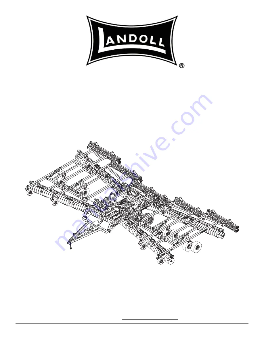
Model 7450

VT Plus

Operator’s Manual

Summary of Contents for 7450 VT Plus

Page 1: ...F 607 0818 LANDOLL CORPORATION 1900 North Street Marysville Kansas 66508 785 562 5381 800 428 5655 WWW LANDOLL COM Model 7450 VT Plus Operator s Manual ...

Page 2: ......

Page 3: ...ations Model Specifications 2 1 General Torque Specifications rev 4 97 2 3 Hydraulic Fitting Torque Specifications 2 4 3 Assembly Instructions Disc Gangs 3 3 Mounting Center Frame Tires and Wheels 3 3 Dual Tire Scraper Installation 3 5 Inner Wing Frames 3 5 Outer Wing Frames 3 7 7450 VT Plus Frame and Hitch Assembly 3 9 Leveler Assembly 3 11 Depth Stop Tube Installation 3 12 Hydraulic Installation...

Page 4: ... 7450 VT Plus 4 6 General Operation 4 7 Field Operation 4 7 Leveling Side to Side 4 8 Leveling Front to Rear 4 10 Hitch Adjustment 4 11 Scraper Adjustment 4 12 Front Gauge Wheels 4 13 Disc Blades 4 14 Depth Stop Adjustment Manual 4 15 7450 VT Wheel Bearing Maintenance 4 16 Center Frame 4 16 Wing Frame 4 17 Hydraulic Maintenance 4 18 Transport 4 18 Lubrication Maintenance 4 21 Storage 4 22 5 Troubl...

Page 5: ... your equipment before using it and describes adjustments needed Gives practical advice for the care and maintenance of your Landoll equipment Drawings in this section locate adjustment points on the equipment IF YOU HAVE ANY QUESTIONS CONTACT LANDOLL CORPORATION 1900 NORTH STREET MARYSVILLE KANSAS 66508 PHONE 785 562 5381 or 800 428 5655 OR FAX 888 527 3909 CHAPTER 5 Is a troubleshooting guide to...

Page 6: ...plement be sure to clean the surface to remove any dirt or residue Where possible sign placement should protect the sign from abrasion damage or obstruction from mud dirt oil etc DANGER Transporting Safety IMPORTANT It is the responsibility of the owner operator to comply with all state and local laws 1 When transporting the implement on a road or highway use adequate warning symbols reflectors li...

Page 7: ...te the skin causing serious injury Use a piece of cardboard rather than hands to search for suspected leaks 2 Any fluid injected into the skin must be surgically removed within a few hours or gangrene may result 3 Avoid the hazard by relieving pressure before disconnecting hydraulic lines Protective Equipment 1 Wear protective clothing and equipment 2 Wear clothing and equipment appropriate for th...

Page 8: ...dem a larger chain may be required Chain capacity must be greater then the TOTAL weight of all towed implements 2 A second chain should be used between each implement 3 Attach the chain to the tractor drawbar support or specified anchor location Allow only enough slack in the chain to permit turning The distance from hitch pin to attachment point or intermediate support point should not exceed 9 i...

Page 9: ...rame 32 1550 X 16 5 Wings 235 75R17 5 Tires W 8 Bolt Walking Dual Wheels Center Frame 32 1550 X 16 5 Wings Spindle Size 4 Center 3 Wings 4 Center 3 Wings 4 Center 3 Wings Wheel Bolt Pattern 8 Bolt 8 Bolt 8 Bolt Estimated Weight W 6 Ga Blade Option 37 170 lbs 39 490 lbs 41 810 lbs NOTE Specifications Are Subject To Change Without Prior Notification Tire Inflation Tire Size Tire Manufacturer Ply Loa...

Page 10: ...ame Nuts Inner Torque to 100 Ft Lbs while rotating Back to loose and tighten by hand until contact is made with bearing Center Frame Nuts Outer 300 Ft Lbs Center Frame Wheel Nuts 450 500 Ft Lbs Wing Frame Wheel Nuts 85 100 Ft Lbs Disc Gang Shafts 1 200 Ft Lbs 5 8 18 Heavy Duty Disc 85 100 Ft Lbs ...

Page 11: ...2 9 16 12 55 62 80 100 110 137 9 16 18 60 75 90 112 130 162 5 8 11 75 94 110 137 170 212 5 8 18 85 106 130 162 180 225 3 4 10 130 162 200 250 280 350 3 4 16 150 188 220 275 320 400 7 8 9 125 156 320 400 460 575 7 8 14 140 175 360 450 500 625 1 8 190 237 408 506 680 850 1 14 210 263 540 675 760 950 1 1 8 7 270 337 600 750 960 1200 1 1 8 12 300 375 660 825 1080 1350 1 1 4 7 380 475 840 1050 1426 178...

Page 12: ... on grade 8 capscrews Use value in if using prevailing torque nuts Parker Brand Fittings Dash Size 37 Degree JIC O Ring ORS O Ring Boss ORB 4 11 13 15 17 13 15 5 14 16 21 23 6 20 22 34 36 25 29 8 43 47 58 62 40 44 10 55 65 100 110 58 62 12 80 90 134 146 75 85 16 115 125 202 218 109 121 20 160 180 248 272 213 237 24 185 215 303 327 238 262 32 250 290 310 340 Gates Brand Fittings Dash Size 37 Degree...

Page 13: ...STANDARD SPECIFICATIONS 2 5 Table provided for general use NOTES ...

Page 14: ...2 6 F 607 0818 STANDARD SPECIFICATIONS Figure 2 1 Wing Stabilizer and Light Bracket Placement 39 Model Left Half 5 50 67236 2 5 725 ...

Page 15: ...STANDARD SPECIFICATIONS 2 7 Figure 2 2 Wing Stabilizer and Light Bracket Placement 39 Model Right Half 5 50 67236 2 5 725 ...

Page 16: ...2 8 F 607 0818 STANDARD SPECIFICATIONS Figure 2 3 Wing Stabilizer and Light Bracket Placement 44 Model Left Half 5 50 67236 2 5 725 ...

Page 17: ...STANDARD SPECIFICATIONS 2 9 Figure 2 4 Wing Stabilizer and Light Bracket Placement 44 Model Right Half 5 50 67236 2 5 725 ...

Page 18: ...2 10 F 607 0818 STANDARD SPECIFICATIONS Figure 2 5 Wing Stabilizer and Light Bracket Placement 49 Model Left Half 5 50 67236 2 5 725 ...

Page 19: ...STANDARD SPECIFICATIONS 2 11 Figure 2 6 Wing Stabilizer and Light Bracket Placement 49 Model Right Half 5 50 67236 2 5 725 ...

Page 20: ...S ARE SAME FOR SPRING OR HYDRAULIC ARM ASSEMBLIES SEE REEL INSTALLATION SECTION IN ASSEMBLY INSTRUCTIONS SECTION FOR ARM ASSEMBLY 14 5 8 7450 39 204522 135 150 REEL ASSEMBLY 7450 39 204416 75 75 DOUBLE REEL 20 3 4 18 1 8 21 1 2 18 3 8 18 3 8 7450 39 204417 90 90 DOUBLE REEL SPRING ARM ASSEMBLY HYDRULIC ARM ASSEMBLY YELLOW REFLECTOR DECAL ...

Page 21: ...F TUBE CLAMPS 14 5 8 21 1 2 18 1 8 20 3 4 7450 39 204422 75 75 DOUBLE REEL 7450 39 204423 90 90 DOUBLE REEL NOTE REEL ASSEMBLIES ARE SAME FOR SPRING OR HYDRAULIC ARM ASSEMBLIES SEE REEL INSTALLATION SECTION IN ASSEMBLY INSTRUCTIONS SECTION FOR ARM ASSEMBLY 7450 39 204522 135 150 REEL ASSEMBLY 18 3 8 18 3 8 NOTE LOCATION OF TUBE CLAMPS 14 5 8 21 1 2 18 1 8 20 3 4 7450 39 204422 75 75 DOUBLE REEL 74...

Page 22: ... ARE SAME FOR SPRING OR HYDRAULIC ARM ASSEMBLIES SEE REEL INSTALLATION SECTION IN ASSEMBLY INSTRUCTIONS SECTION FOR ARM ASSEMBLY 13 5 8 7450 44 204522 135 150 REEL ASSEMBLY 7450 44 204417 90 90 DOUBLE REEL 20 3 4 20 1 8 22 1 2 18 3 8 18 3 8 7450 44 204418 105 105 DOUBLE REEL SPRING ARM ASSEMBLY HYDRULIC ARM ASSEMBLY YELLOW REFLECTOR DECAL ...

Page 23: ...ARM ASSEMBLIES SEE REEL INSTALLATION SECTION IN ASSEMBLY INSTRUCTIONS SECTION FOR ARM ASSEMBLY 7450 44 204522 135 150 REEL ASSEMBLY 18 3 8 18 3 8 NOTE LOCATION OF TUBE CLAMPS 13 5 8 22 1 2 20 1 8 20 3 4 7450 44 204423 90 90 DOUBLE REEL 7450 44 204424 105 105 DOUBLE REEL SPRING ARM ASSEMBLY HYDRULIC ARM ASSEMBLY YELLOW REFLECTOR DECAL ...

Page 24: ... ARE SAME FOR SPRING OR HYDRAULIC ARM ASSEMBLIES SEE REEL INSTALLATION SECTION IN ASSEMBLY INSTRUCTIONS SECTION FOR ARM ASSEMBLY 12 5 8 7450 49 204522 135 150 REEL ASSEMBLY 7450 49 204418 105 105 DOUBLE REEL 20 3 4 22 1 8 23 1 2 18 3 8 18 3 8 7450 49 204419 120 120 DOUBLE REEL SPRING ARM ASSEMBLY HYDRULIC ARM ASSEMBLY YELLOW REFLECTOR DECAL ...

Page 25: ...RM ASSEMBLIES SEE REEL INSTALLATION SECTION IN ASSEMBLY INSTRUCTIONS SECTION FOR ARM ASSEMBLY 7450 49 204522 135 150 REEL ASSEMBLY 18 3 8 18 3 8 NOTE LOCATION OF TUBE CLAMPS 12 5 8 23 1 2 22 1 8 20 3 4 7450 49 204424 105 105 DOUBLE REEL 7450 49 204425 120 120 DOUBLE REEL SPRING ARM ASSEMBLY HYDRULIC ARM ASSEMBLY YELLOW REFLECTOR DECAL ...

Page 26: ...2 18 F 607 0818 STANDARD SPECIFICATIONS Figure 2 13 Dual Tire Scraper Installation 6 7 7 75 6 5 3 5 3 7 86 21 287 5 7 5 6 21 ...

Page 27: ...STANDARD SPECIFICATIONS 2 19 Figure 2 14 Rear Tow Hitch Installation MOUNTING SCREWS WILL LOCATE HITCH HOSES AND WIRING ON THIS SIDE WILL BE ROUTED THROUGH TUBE 50 7450 rear hitch placement ...

Page 28: ...2 20 F 607 0818 STANDARD SPECIFICATIONS Table provided for general use NOTES ...

Page 29: ...ee General Torque Specifications rev 4 97 on page 2 3 CAUTION DANGER WARNING DANGER Be sure to bleed the hydraulic system of all air in lines after installation Failure to bleed the system of all air can result in improper machine operation Disc blades are extremely sharp Exercise extreme care when working on or near disc blades Do not allow discs to roll over or fall onto any bodily part Do not a...

Page 30: ... SCREW 3 4 10 X 5 1 2 HEX HEAD CAP SCREW 3 4 10 X 9 HEX HEAD CAP SCREW LEFT CENTER REAR DISC GANG ASSEMBLY 3 4 10 X 9 HEX HEAD CAP SCREW 3 4 10 X 2 1 4 HEX HEAD CAP SCREW CLAMP PLATE INSIDE TUBE 3 4 10 HEX LOCK NUT LEFT CENTER FRONT DISC GANG ASSEMBLY 7450 center frame disc gang inst 3 4 10 X 8 HEX HEAD CAP SCREW 3 4 10 X 2 HEX HEAD CAP SCREW MANIFOLD MOUNT BRACKET NOTE INSTALL RH LH LIGHT BRACKET...

Page 31: ...he studs being careful not to damage the stud threads Make sure that the disc wheel is flat against the mounting surface There will be a wheel spacer on the hub and it needs to be mounted between the hub and the inner wheel NOTE Do not put hub spacer between the wheels 3 Position the outer disc wheel being careful not to damage the stud threads Be sure the valve stems for both the inner and outer ...

Page 32: ... 7 11 5 1 17 5 5 0 7 11 5 1 3 6 5 2 187 7 5 1 66 0 03 3 7 7 11 5 1 5 5 6 66 0 7 11 5 1 5217 6 66 0 6 7 1 2 66 0 3 6 5 3 6 5 2 187 2 187 1 67 5 5217 02817 58 5 803 5 1 5 67 02817 3 6 5 6 5 6 0867 3 83 5 LQQHU JDQJ LQVW 7 3 6 5 1 3 1 5266 3 1 2 187 7 6 5 7 5867 6 5 6 277 187 52 3 1 ...

Page 33: ... 4 10 x 8 1 2 hex head cap screws and hex lock nuts See Figure 3 3 2 Assemble the tire and wheel assemblies p n 156952 to the wing frames The wings use 12 5L x 15 GY FI load range F tires with 8 bolt wheels and 2 1 4 slip in spindles Torque to 85 to 100 ft lbs 3 Assembly wing stabilizer and wing lock as shown on the front and rear cross tubes IMPORTANT Note the orientation as the rubber bumper mus...

Page 34: ... LOCK NUT LEFT OUTER WING DISC GANG ASSEMBLY LEFT OUTER WING DISC GANG ASSEMBLY REAR FRONT SEE DETAIL A DETAIL A 7450 49 outer gang inst 1 3 4 THRUST WASHER DOUBLE HINGE 1 8 X 6 1 2 HEX HEAD CAP SCREW HINGE PIN 1 3 4 X 9 3 4 1 3 4 SNAP RING 1 1 2 X 4 3 8 WING FOLD SPACER 1 8 HEX LOCK NUT FOLD LINK 1 1 4 7 HEX LOCK NUT GANG SHAFT WASHER 1 3 4 X 9 3 8 LOCK PIN 1 3 4 X 9 3 4 HINGE PIN 1 3 4 SNAP RING...

Page 35: ...mblies p n 156952 to the wing frames The wings use 12 5L x 15 GY FI load range F tires with 8 bolt wheels and 2 1 4 slip in spindles Torque to 85 to 100 ft lbs NOTE All tire wheel assemblies are mounted with the valve stem facing outward 4 Install disc gangs to inner wing frames using 3 4 10 x 2 hex head cap screws and hex lock nuts Figure 3 6 Thrust Washer Locations Figure 3 7 Outer Wing Frame Hi...

Page 36: ...HOLDER WING NUT HOSE HOLDER CLAMP 3 8 16 HEX NUT HOSE HOLDER BRACKET 3 8 16 X 3 1 2 ALL THREAD SCREW 1 4 20 HEX LOCK NUT HITCH RING 41 000 LB SAFETY CHAIN 1 4 20 X 1 HEX HEAD CAP SCREW 1 2 13 X 12 HEX HEAD CAP SCREW HITCH 1 2 13 X 11 HEX HEAD CAP SCREW 3 4 10 X 10 1 2 HEX HEAD CAP SCREW 1 1 2 6 HEX NUT 1 1 2 6 SPLIT LOCK WASHER 1 1 2 THRUST WASHER HITCH MOUNT PLATE 1 1 2 6 X 11 HEX HEAD CAP SCREW ...

Page 37: ...que flange nut with the flange pointing upward as well Do not tighten this cap screw so the hose holder bracket may pivot freely in this joint 4 Slide the hose holder bracket over the screw and secure with another 3 4 prevailing torque flange nut 5 Install a 3 8 16 x 3 1 2 all thread screw in the front of the hose holder bracket and secure with a 3 8 16 hex nut 6 Slide the hose holder clamp over t...

Page 38: ...LOCK WASHER LEVELER BALL JOINT LINK 1 1 2 6 X 6 HEX HEAD CAP SCREW 1 1 2 FLAT WASHER 90 ELBOW W 1 32 RESTRICTOR LEVELER ASSEMBLY 3 4 10 HEX LOCK NUT LEVELER PIN KEEPER 3 4 10 X 2 1 4 HEX HEAD CAP SCREW 1 1 4 X 6 3 8 LEVELER PIN 1 2 13 X 6 1 2 HEX HEAD CAP SCREW HITCH PIN PIN IN FRONT HOLE OF LEVELER ASSEMBLY DURING NORMAL OPERATION 1 2 X 2 1 4 GROOVED ALLOY PIN CENTER LEFT LIFT LEVELER TOWER LEVEL...

Page 39: ...nd of the leveler tube Drawbars of 17 or less could require the 2nd hole in 6 Attach leveler tower to the top of the leveler ball joint link with hitch pin 1 2 x 2 1 4 grooved alloy pin 2 1 1 2 washers and 1 8 hex lock nut 7 Attach the leveler ball joint link to the lower hole of the lower hole of the hitch plate with a 1 1 2 6 x 6 hex head cap screw split lock washer and hex nut See Figure 3 9 NO...

Page 40: ... center lift and secure with a 5 8 11 hex lock nut 3 Insert 90º elbow fitting in the front of the limit valve 4 Using 5 16 18 x 5 hex head cap screws secure the front end of the depth stop tube assembly to the top of the frame mount with the depth stop guide slide pad and 5 16 18 hex lock nuts Attach the limit valve to the bottom side of the center frame mount using these same screws IMPORTANT It ...

Page 41: ...LY 4 1 2 X 16 HYD REPHASE CYLINDER 3 8 X 31 HOSE ASSEMBLY 3 8 X 96 HOSE ASSEMBLY 3 8 X 24 HOSE ASSEMBLY 3 8 X 120 HOSE ASSEMBLY 3 8 X 86 HOSE ASSEMBLY 3 8 X 212 HOSE ASSEMBLY 1 2 X 49 HOSE ASSEMBLY 1 2 X 230 HOSE ASSEMBLY 1 2 X 271 HOSE ASSEMBLY 3 8 X 285 HOSE ASSEMBLY FRONT MANIFOLD ASSEMBLY 3 4 16 MALE COUPLER SEE DETAIL A DETAIL A 90 ADAPTER 3 8 X 24 HOSE ASSEMBLY 1 000 PSI RELIEF VALVE ADAPTER...

Page 42: ...ASSEMBLY 3 8 X 130 HOSE ASSEMBLY 3 8 X 116 HOSE ASSEMBLY 3 8 X 64 HOSE ASSEMBLY 3 8 X 42 HOSE ASSEMBLY 3 8 X 24 HOSE ASSEMBLY 3 8 X 100 HOSE ASSEMBLY 3 8 X 96 HOSE ASSEMBLY 3 4 16 MALE COUPLER 3 8 X 276 HOSE ASSEMBLY 3 8 X 20 HOSE ASSEMBLY 3 8 X 72 HOSE ASSEMBLY 3 8 X 156 HOSE ASSEMBLY 3 8 X 27 HOSE ASSEMBLY 3 8 X 36 HOSE ASSEMBLY 3 8 X 72 HOSE ASSEMBLY 3 8 X 10⁵ HOSE ASSEMBLY 3 8 X 190 HOSE ASSEM...

Page 43: ... 3 8 X 24 HOSE ASSEMBLY 4 1 2 X 16 HYD REPHASE CYLINDER 3 8 X 31 HOSE ASSEMBLY 3 8 X 96 HOSE ASSEMBLY 3 8 X 24 HOSE ASSEMBLY 3 8 X 136 HOSE ASSEMBLY 3 8 X 10⁵ HOSE ASSEMBLY 3 8 X 244 HOSE ASSEMBLY 1 2 X 49 HOSE ASSEMBLY 1 2 X 230 HOSE ASSEMBLY 1 2 X 271 HOSE ASSEMBLY 3 8 X 312 HOSE ASSEMBLY 90 ADAPTER FRONT MANIFOLD ASSEMBLY 3 4 16 MALE COUPLER SEE DETAIL A 3 8 X 24 HOSE ASSEMBLY 1 000 PSI RELIEF ...

Page 44: ...ASSEMBLY 3 8 X 146 HOSE ASSEMBLY 3 8 X 123 HOSE ASSEMBLY 3 8 X 64 HOSE ASSEMBLY 3 8 X 42 HOSE ASSEMBLY 3 8 X 24 HOSE ASSEMBLY 3 8 X 100 HOSE ASSEMBLY 3 8 X 114 HOSE ASSEMBLY 3 4 16 MALE COUPLER 3 8 X 276 HOSE ASSEMBLY 3 8 X 20 HOSE ASSEMBLY 3 8 X 72 HOSE ASSEMBLY 3 8 X 168 HOSE ASSEMBLY 3 8 X 27 HOSE ASSEMBLY 3 8 X 36 HOSE ASSEMBLY 3 8 X 72 HOSE ASSEMBLY 3 8 X 10⁵ HOSE ASSEMBLY 3 8 X 206 HOSE ASSE...

Page 45: ... 3 8 X 24 HOSE ASSEMBLY 4 1 2 X 16 HYD REPHASE CYLINDER 3 8 X 31 HOSE ASSEMBLY 3 8 X 96 HOSE ASSEMBLY 3 8 X 24 HOSE ASSEMBLY 3 8 X 146 HOSE ASSEMBLY 3 8 X 116 HOSE ASSEMBLY 3 8 X 267 HOSE ASSEMBLY 1 2 X 49 HOSE ASSEMBLY 1 2 X 230 HOSE ASSEMBLY 1 2 X 271 HOSE ASSEMBLY 3 8 X 340 HOSE ASSEMBLY 3 8 X 24 HOSE ASSEMBLY 1 000 PSI RELIEF VALVE ADAPTER 3 8 X 140 HOSE ASSEMBLY TO BASE WING STR SWIVEL FITTIN...

Page 46: ...C CYLINDERS P N 167575 3 8 X 228 HOSE ASSEMBLY 3 8 X 159 HOSE ASSEMBLY 3 8 X 159 HOSE ASSEMBLY 3 8 X 64 HOSE ASSEMBLY 3 8 X 42 HOSE ASSEMBLY 3 8 X 24 HOSE ASSEMBLY 3 8 X 100 HOSE ASSEMBLY 3 8 X 128 HOSE ASSEMBLY 3 4 16 MALE COUPLER 3 8 X 276 HOSE ASSEMBLY 3 8 X 20 HOSE ASSEMBLY 3 8 X 72 HOSE ASSEMBLY 3 8 X 185 HOSE ASSEMBLY 3 8 X 27 HOSE ASSEMBLY 3 8 X 36 HOSE ASSEMBLY 3 8 X 72 HOSE ASSEMBLY 3 8 X...

Page 47: ... 1 2 3 0 1 0 1 1 5217 0 1 2 66 0 5 5 0 1 2 66 0 5 4 75 163257 2 5 8 6 7 26 520 0 1 2 26 2 1 72 5 5 2 1 5 1 5 1 5 26 66 0 26 66 0 26 66 0 1 5 5217 2 0 1 5217 2 0 1 7 2 5 675 725 37 5 7 6 9 37 5 75 21 2 2 5 675 725 37 5 7 6 9 37 5 7 6 9 37 5 75 21 2 7 6 9 37 5 37 5 1 5 5217 8 9 6 7 5217 2 0 1 4 5 4 5 ...

Page 48: ...ER 1 1 4N FLAT WASHER 5 16 X 2 1 2 SPRING SLOTTED PINS 39 OR ROLL PINS PROVIDED W CYLINDER 44 49 2 WING FOLD SPACER 1 2 WIDE 1 1 4 X 9 9 16 FOLD PIN WING FOLD ROLLER 1 3 16 WIDE 1 1 4W FLAT WASHER 7450 49 cylinder pins 1 1 4 X 6 1 8 FOLD PIN 39 OR CLEVIS PIN PROVIDED W CYLINDER 44 49 BASE END OF ALL CYLINDERS DETAIL A 2 WING FOLD SPACER 1 2 WIDE WING FOLD ROLLER 1 3 16 WIDE 1 1 4W FLAT WASHER SEE ...

Page 49: ... be left unassembled until fold hydraulic system is fully charged with oil to prevent machine damage 5 Install 90 degree regular adapter fittings in both ends of all lift cylinders and transport lock cylinders 4 1 2 x 16 4 x 16 3 3 4 x 16 3 1 2 x 8 and 3 1 4 x 8 CAUTION 6 Install the 16 port front manifold to the manifold bracket on the front of the center frame using 1 2 13 x 3 1 2 hex head cap s...

Page 50: ...ASHER CONTROL MODULE RH BRACKET WELDMENT 1 4 20 X 1 1 4 HEX HEAD CAP SCREW AG RED SINGLE LED LAMP U BOLT SMV MOUNTING BRACKET 5 8 11 FLANGE HEAD SERRATED NUT REAR WARNING LIGHT HARNESS 1 4 20 X 1 1 2 HEX HEAD CAP SCREW 1 4 20 HEX LOCK NUT 7 PIN CONN 1 2 3 4 5 6 7 D B A C GROUND WORK LAMPS LEFT FLASHING TURN STOP LAMPS RIGHT FLASHING TURN TAIL LAMPS SWITCHED POWER 12V 4 PIN TOWER GROUND BLACK YELLO...

Page 51: ...nuts The SMV sign should be mounted as shown in light bracket placements See Figures 2 1 thru 2 6 Rear Tow Hitch Installation Refer to Figure 2 14 for rear tow hitch placement 1 Attach rear tow hitch assembly to center frame using hitch plates mount plate 3 4 10 x 8 1 2 hex head cap screws 3 4 10 x 9 1 2 hex head cap screws and 3 4 10 hex lock nuts See Figure 3 22 2 Move SMV from frame to rear tow...

Page 52: ...assembly to reel arm using 1 pivot pin and 5 16 x 1 1 2 spring slotted pins Set pin centers to 21 dimension as shown in Figure 3 24 On the outer wings the reel arm stop will replace the machinery bushing on the outside of the reel arm See Figure 3 23 This will prevent the outer reels from hanging down so far while the machine is being folded Refer to pages 2 6 thru 2 17 for reel arm stop locations...

Page 53: ...AVY SPRING ASSEMBLY 1 8 HEX LOCK NUT 1 LOCK WASHER ADJUSTMENT PIN SNAP RING 1 X 8 ADJUSTMENT BOLT 1 1 2 FLANGE BEARING 1 1 2 PIVOT BUSHING 5 16 X 1 1 2 SPRING SLOTTED PIN PIVOT PIN MACHINERY BUSHING REEL ARM 3 4 10 HEX LOCK NUT DOUBLE NUT REEL GANG BAR ASSEMBLY 21 NOTE SIDE PLATE REMOVED FOR CLARITY GANGBAR MOUNT PLATE 3 4 10 X 6 HEX HEAD CAP SCREW ...

Page 54: ...onditioner Double Reel Installation 28 5 66 0 1 5 02817 3 7 635 1 66 0 5 1 1 3 927 86 1 52 3 1 3 927 3 1 0 1 5 86 1 28 5 50 2 187 03 78 635 1 7256 21 58 5 03 78 3 6 5 2 1876 3 6 5 2 1876 03 78 187 2 6 5 8670 17 3 1 61 3 5 1 2 7 3 6 5 635 1 7256 21 58 5 ...

Page 55: ... HOSE ASSEMBLY 1 4 X 75 HOSE ASSEMBLY 1 4 X 36 HOSE ASSEMBLY 1 4 X 40 HOSE ASSEMBLY 1 4 X 54 HOSE ASSEMBLY 1 4 X 50 HOSE ASSEMBLY 1 4 X 78 HOSE ASSEMBLY 1 4 X 10² HOSE ASSEMBLY 1 4 X 68 HOSE ASSEMBLY 1 4 X 75 HOSE ASSEMBLY 90 ADAPTER B A 90 JIC SWIVEL ADAPTER BULKHEAD RUN TEE 1 4 X 48 HOSE ASSEMBLY 1 4 X 60 HOSE ASSEMBLY 1 4 X 120 HOSE ASSEMBLY 90 ADAPTER 8 PORT MANIFOLD ASSEMBLY MANIFOLD MOUNT 1 ...

Page 56: ...4 X 78 HOSE ASSEMBLY 1 4 X 75 HOSE ASSEMBLY 1 4 X 40 HOSE ASSEMBLY 1 4 X 34 HOSE ASSEMBLY 1 4 X 54 HOSE ASSEMBLY 1 4 X 50 HOSE ASSEMBLY 1 4 X 78 HOSE ASSEMBLY 1 4 X 116 HOSE ASSEMBLY 1 4 X 57 HOSE ASSEMBLY 90 ADAPTER 1 4 X 75 HOSE ASSEMBLY B A 90 JIC SWIVEL ADAPTER BULKHEAD RUN TEE 1 4 X 48 HOSE ASSEMBLY 1 4 X 75 HOSE ASSEMBLY 1 4 X 120 HOSE ASSEMBLY 90 ADAPTER 8 PORT MANIFOLD ASSEMBLY MANIFOLD MO...

Page 57: ...X 78 HOSE ASSEMBLY 1 4 X 75 HOSE ASSEMBLY 1 4 X 40 HOSE ASSEMBLY 1 4 X 34 HOSE ASSEMBLY 1 4 X 54 HOSE ASSEMBLY 1 4 X 50 HOSE ASSEMBLY 1 4 X 78 HOSE ASSEMBLY 1 4 X 130 HOSE ASSEMBLY 90 JIC SWIVEL ADAPTER BULKHEAD RUN TEE 1 4 X 48 HOSE ASSEMBLY 1 4 X 90 HOSE ASSEMBLY 1 4 X 120 HOSE ASSEMBLY 90 ADAPTER 8 PORT MANIFOLD ASSEMBLY MANIFOLD MOUNT 1 2 13 X 3 1 2 HEX HEAD CAP SCREW AND HEX LOCK NUT ADAPTER ...

Page 58: ...l use the longer trunnion mounts a reel arm stop and a trunnion stop with 1 2 13 x 2 1 4 hex head cap screws and split lock washer See 3 32 and 3 29 and See 3 33 for double reel See Figures 2 1 thru 2 12 for reel arm stop locations Figure 3 29 Conditioner Reel Arm Stop 3 Install 1 8 hex nut onto rod of cylinder and install 17 heavy spring assembly onto cylinder rod 4 Install 1 1 2 flange bearing i...

Page 59: ...CREW 1 8 HEX NUT 17 HEAVY SPRING ASSEMBLY 1 8 HEX LOCK NUT 1 LOCK WASHER ADJUSTMENT PIN SNAP RING 1 X 8 ADJUSTMENT BOLT 1 1 2 FLANGE BEARING 1 1 2 PIVOT BUSHING 5 16 X 1 1 2 SPRING SLOTTED PIN PIVOT PIN MACHINERY BUSHING REEL ARM 3 4 10 HEX LOCK NUT DOUBLE NUT REEL GANG BAR ASSEMBLY 21 NOTE SIDE PLATE REMOVED FOR CLARITY GANGBAR MOUNT PLATE 3 4 10 X 6 HEX HEAD CAP SCREW ...

Page 60: ...LATE 1 8 HEX LOCK NUT 2 1 2 x 1 HYDRAULIC CYLINDER 45 OR STRAIGHT ADAPTER 1 2 13 X 1 1 2 HEX HEAD CAP SCREW 1 2 SPLIT LOCK WASHER 1 1 2 FLANGE BEARING REEL ARM 1 1 2 PIVOT BUSHING MACHINERY BUSHING PIVOT PIN 5 16 X 1 1 2 SPRING SLOTTED PIN 3 4 10 HEX LOCK NUT DOUBLE NUT REEL GANG BAR ASSEMBLY 17 HEAVY SPRING ASSEMBLY 1 8 HEX NUT 90 ADAPTER CYLINDER TRUNNION NOTE REEL ARM STOP IS ONLY USED ON OUTER...

Page 61: ...itioner Double Reel Installation Option 28 5 66 0 1 5 02817 3 7 7 635 1 66 0 1 21 6 7 6 5 1 5 3 6 5 3 6 5 5 1 1 3 927 86 1 52 3 1 3 927 3 1 0 1 5 86 1 5 50 2 6 5 75811 21 02817 66 2 187 03 78 635 1 7256 21 58 5 03 78 3 6 5 2 1876 3 6 5 2 1876 03 78 0 187 ...

Page 62: ...3 34 Finishing Conditioner Reel Installation Hydraulic Hose Placement Left Half Figure 3 35 Finishing Conditioner Reel Installation Hydraulic Hose Placement Right Half BULKHEAD RUN TEE SMALL LOOP 7450 reel 5 7450 reel 4 BULKHEAD RUN TEE SMALL LOOP ...

Page 63: ...11 Install hoses per Figures 3 26 through 3 28 Hose routing to follow Figures 3 34 and 3 35 12 Install hose clamp brackets as shown at hinge lines with 1 2 13x1 1 2 round head square neck bolts and nuts Assemble hose clamp with 3 8 16 x 1 1 2 bolts and 3 8 flange lock nuts See Figure 3 38 Figure 3 38 Gang Bar Hose Clamp Placement 13 Install other hose clamps as needed to secure hoses NOTE The oute...

Page 64: ...nt damage Follow instructions for charging the hydraulic fold system as described in Hydraulic Fold System on page 4 5 4 Connect lights to the tractor and verify operation 5 Check tires for proper inflation 6 Level the implement from side to side as described in Leveling Side to Side on page 4 8 7 Inspect the final implement assembly and verify that all bolts have been tightened cotter pins spread...

Page 65: ...equipment is idle Failure to take preventive measures against accidental lowering can result in serious personal injury Always lock the tractor drawbar in the center position when transporting the unit Failure to do so can result in serious injury or death and cause damage to the equipment When transporting the unit place cylinder lockouts in the transport lock position after fully extending the c...

Page 66: ...on VT Plus Preparation Figure 4 1 Disc Scraper to Disc Blade 1 Prior to operating the 7450 VT Plus inspect it thoroughly for good operating condition 2 Replace worn or missing parts 3 When the machine is new check the bolt tightness after a few hours of operation Tighten any loose nuts or bolts Check the lift wheel lug bolts daily 4 Check the lift wheel tire inflation Inflate all tires equally to ...

Page 67: ...maller wing frame cylinders plumbed in series with larger center frame cylinders It is important that the cylinders be connected in the proper series for the lift system to operate correctly When the cylinders are fully extended and held in this position oil is able to flow through the cylinders or rephase and allow the cylinders to operate in sync This also allows the system to purge any air that...

Page 68: ...or reservoir to make sure it is within operating limits 3 Always fully extend the cylinders and hold the lever to ensure the cylinders are rephased before starting any field operation This will keep all cylinders in time and frame sections level when operating 4 The transport locks for the hydraulic lift system are plumbed into the fold system During folding they are activated to lock the machine ...

Page 69: ...ers several times The cylinder rod travel should be smooth and positive when all air has been purged from the system Due to large amounts of hydraulic oil required recheck the tractor fluid level to make sure it is within proper operating limits 4 The hydraulic fold system is equipped with restrictors in the rod end of cylinders to prevent uncontrolled falling of wing frames when unfolding Removal...

Page 70: ...when unfolding will result in serious damage to the implement Be sure other people and pets are a safe distance away 2 Fully raise the folded machine to unhook the locks and continue to hold the lever to fully extend the wing transport wheels See Figures 4 6 and 4 7 3 Unfold the machine Transport locks will disengage from the center lifts during the unfolding process 4 Continue to hold lever until...

Page 71: ...of each frame section and to control the leveling feature Maximum discing depth cannot be achieved by raising the lift wheels off the ground Little or no weight on the lift wheels will cause the frame sections to gouge side draft and buckle producing inconsistent cutting depth 4 Do not turn with the VT Plus in the ground this can put excessive side load on the gangs and hitch Raise the unit slight...

Page 72: ...ades are 1 off the ground d Measure the distance from the walking beam spindle to the top of the frame on both sides If there is a difference it needs to be adjusted by turning the cylinder rods with the wrench flats provided at the clevis end See Figure 4 9 e Let the machine down onto the ground to relieve any pressure but do not fully retract the cylinders f Loosen the set screw in the cylinder ...

Page 73: ...e in the walking beam to the top side of the frame See Figure 4 10 e On the wing frame measure the distance from the welded washer to the top side of the wing frame See Figure 4 11 f Measure the same distance on the wing frame The wing frames are generally set to the same distance or slightly higher than the center frame The 7450 requires subtracting 1 from the center frame measurement for the win...

Page 74: ...the rear gangs are too deep If there is a furrow left from the rear gangs the front gangs are too deep 3 Implements with the hydraulic leveler can make adjustments on the go from the tractor A reference gauge is provided on the implement for a guide 4 For normal operation the leveler will be set in the bottom hole on the lift and the outer hole on the leveler tube See Figure 4 13 IMPORTANT Imprope...

Page 75: ...he ground b Adjust the hydraulic leveler in or out until the pressure is relieved on the leveling system See Leveling Side to Side on page 4 8 and Leveling Front to Rear on page 4 10 c Remove the 1 1 2 6 X 6 hex head cap screw and hardware from the leveler ball joint link at the center rear of the hitch weldment d Loosen but do not remove the bolts that pass through the welded bushing at the outer...

Page 76: ...eel In wet conditions the scraper may be set against the disc blade and will function as a spring loaded scraper 2 Scraper blades have two positions and are reversible The blades are initially set in the front position to position scraper closer to the spool This position will perform better in wet and heavier residue conditions The blade may be moved back for dryer conditions and climates where l...

Page 77: ...ter ridge 3 To adjust the gauge wheel depth loosen and adjust the nuts on the top and bottom of the frame tube See Figure 4 17 The top nut will have to be loosened first allowing the bottom nut to descend out of its locked position so that it can be rotated Once the bottom nut is adjusted up or down retighten the top nut being sure the bottom one is inside of the lock A wrench is provided on the i...

Page 78: ...harpening more difficult often with mixed results and is not covered by warranty Disc blade manufacturers will not cover any alterations to blades other than the place of manufacture Results from roll sharpening damage may not be immediate and may take more than a season to be noticeable If you choose to sharpen disc blades check with local dealers for reputable experienced sharpeners that will st...

Page 79: ... One turn will equal approximately 1 8 adjustment in depth 2 The gauge on the side of the depth stop tube gives a reference for depth setting The A setting refers to maximum operating depth IMPORTANT For maximum operating depth the lift wheels must be in contact with the ground and carry some of the machine weight Raising the lift wheels off the ground permits uncontrolled depth of each frame sect...

Page 80: ...E LIP GREASE SEAL INNER BEARING CONE INNER BEARING CUP 8 BOLT HUB OUTER BEARING CUP OUTER BEARING CONE SPINDLE WASHER 1 14 HEX SLOT NUT HUB CAP 2 1 4 SPINDLE 3 16 X 1 1 2 COTTER PIN 7450 wheel bearing maintenance 7450 CENTER FRAME WHEELS 7450 WING FRAME WHEELS 4 X 22 1 4 SPINDLE 4 5 8 TRIPLE TEFLON SEAL INNER BEARING CONE SLEEVE ASSEMBLY INNER BEARING CUP 8 BOLT HUB INNER SPIN NUT TONGUE WASHER DE...

Page 81: ...r washer side 16 Torque outer nut to 300 ft lbs Endplay of 001 to 010 must be present in the adjust wheel bearing assembly 17 Bend over one tab of star washer that is aligned with a flat on the outer nut to prevent rotation 18 Grease interior of cap lightly to prevent any corrosion 19 Install the hub cap with the proper gasket Tighten the cap screws of the hub cap to 15 to 20 ft lbs of torque 20 R...

Page 82: ... and follow all federal state and local requirements before transporting the VT Plus 2 The 7450 should be transported only by tractor required for field operation The implement weight should not exceed more than 1 5 times the tractor weight Refer to Standard Specifications on page 2 1 for estimated weight of each model Maximum transport speed for the 7450 is 20 mph for the implement and is designa...

Page 83: ...fore transporting Check wheel lug bolts to insure tightness Figure 4 21 Hitch Speed Identification Symbol and Safety Chain 8 Know the transport heights and widths of the unit before transporting Attachments such as leveling harrows can increase the transport dimensions of the implement Use caution when transporting near bridges and power lines WARNING 9 Raise the unit to full transport height 10 I...

Page 84: ...OF LUBE POINTS INTERVAL Hours Unless Stated 1 Disc Gang Bearings 1 each 10 2 Conditioner Reel Bearings 1 each 10 3 Walking Tandem Hubs 2 each Top Bottom 10 4 Wing Wheel Hubs 1 each 50 5 Front Gauge 6 Bolt Wheel Hubs 1 each 50 6 Leveler Assembly 1 50 7 4 1 2 x 16 Lift Cylinder Rod Block 2 50 8 Gauge Wheel Pivot 4 10 7450 lube 7 2 1 3 6 5 4 8 ...

Page 85: ...m the seal Regular lubrication will maintain a full grease cavity and help purge any contaminants Grease the bearings before long periods of storage to prevent moisture buildup within the bearing cavity 4 Center frame hubs do not require regular lubrication Inspect annually for wear and replace or clean and relubricate as necessary For wheel bearing maintenance refer to Center Frame on page 4 16 5...

Page 86: ...iscs e Apply a light coating of oil or grease to exposed cylinder rods to prevent them from rusting f Lubricate each point of the machine as stated in Lubrication Maintenance on page 4 21 2 Store the unit in a shed or under a tarpaulin to protect it from the weather The ground tools and tires should rest on boards or some other object to keep them out of the soil 3 If the unit must be stored outsi...

Page 87: ... Hitch adjustment too high Lower implement hitch point Gauge wheels too high allowing wings to go to deep Properly reset gauge wheels UNEVEN DEPTH Frame not level side to side Level center frame side to side Wing frames and center frame not level Level wing frames to center frame Lift cylinders not in phase Fully extend lift cylinders and hold hydraulic lever until all cylinders are fully extended...

Page 88: ...alve not working Repair valve HYDRAULIC UNIT SETTLING ONE WING RAISING Center frame cylinder leaking internally on side of unit that wing is raising Repair center master cylinder HYDRAULIC WING SETTLING Wing cylinder leaking Repair cylinder DISC GANG PLUGGING Scrapers set too far from disc blade Adjust scrapers to meet disc blade closer and evenly Operating depth too deep Raise unit Conditions too...

Page 89: ......

Page 90: ... facilities Model 7450 VT Plus Operator s Manual Re Order Part Number F 607 0818 LANDOLL CORPORATION 1900 North Street Marysville Kansas 66508 785 562 5381 800 428 5655 WWW LANDOLL COM F 607 0818 Copyright 2010 Landoll Corporation All rights reserved including the right to reproduce this material or portions thereof in any form ...

Reviews: