FOGLIO ISTRUZIONI
DATI TECNICI
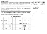
TECHNICAL DATA
INSTRUCTION LEAFLET
ITA
ENG
Cod.
Potenza /
Power
Tensione /
Voltage
Lumen
Kelvin
CRI
Fascio /
Beam angle
IP
Lunghezza /
Lenght
Larghezza /
Width
Spessore /
Thickness
REEL230V10BC
13W
AC 220-240V; 50Hz
1500 Lm/W
3000K
>80Ra
120°
IP65
10000 mm
13,55 mm
4,85 mm
REEL230V10BN
13W
AC 220-240V; 50Hz
1500 Lm/W
4000K
>80Ra
120°
IP65
10000 mm
13,55 mm
4,85 mm
REEL230V50BC
13W
AC 220-240V; 50Hz
1500 Lm/W
3000K
>80Ra
120°
IP65
50000 mm
13,55 mm
4,85 mm
REEL230V50BN
13W
AC 220-240V; 50Hz
1500 Lm/W
4000K
>80Ra
120°
IP65
50000 mm
13,55 mm
4,85 mm
Il presente foglio istruzioni va conservato per future consultazioni. Assicurarsi di leggere e comprendere le istruzioni prima dell’installazione.
This instruction sheet have to be kept for future consultations. Be sure to read and understand the instructions before installation.
made in P.R.C.
IMPORTED BY:
LAMPO LIGHTING TECHNOLOGY SRL
Via dell’industria 6, 47832 San Clemente RN ( ITALY )
www.lampolighting.com
Assicurarsi che l’Input Line sia collegato alla Striscia LED e isolato con del silicone sigillante.
Lunghezza massima alimentabile con un singolo Input Line: 70 metri.
Make sure that the Input Line is firmly connected to the LED Strip and insulated with silicone sealant.
Maximum length that can be fed with a single Input Line: 70 meters.
Installazione di un nuovo Input Line (fig. 1)
(REEL230VKITPLUG)
1.
Installing a new Input Line (fig. 1)
(REEL230VKITPLUG)
Fare leva con un cacciavite a taglio per staccare il
coperchio dalla base (fig. 2)
2.
Pry with a flat screwdriver to detach the cover from the base
(fig. 2)
INSTALLAZIONE
INSTALLATION
REEL230V
il simbolo indica che il prodotto non deve essere smaltito come rifiuto non selezionato ma
deve essere inviato a strutture di raccolta separate per il recupero e il reciclaggio
the symbol indicates that the product must not be disposed of as unsorted waste but
must be sent to separate collection facilities for recovery and recycling
DISEGNO TECNICO
TECHNICAL DRAWING
ACCESSORI OPZIONALI
(NON INCLUSI)
:
Optional accessories (not included):
COD
. REEL230VCAP
• nr.1 TAPPO DI CHIUSURA IN PVC
PVC end cap
COD
. REEL230VKITCLIP
• nr.20 VITI
Screws
• nr.10 CLIP IN PVC
Install pvc clip
COD
. SIL7G
• nr.1 TUBETTO SILICONE 7g
7g silicon gluewater
COD
. REEL230VCONFF
• nr.1 CONNETTORE RAPIDO IN PVC
DI CONGIUNZIONE /
PVC connector
• nr.1 TUBETTO SILICONE 7g
7g silicon gluewater
COD
. REEL230VKITPLUG
• nr.1 TAPPO DI CHIUSURA IN PVC
PVC end cap
• nr.1 SPINA SCHUKO CAVO 50cm, DRIVER 8A CON FUSIBILE, CONNETTORE
White Schuko plug with 50cm wire, 8A driver wit fuse, connector
• nr.1 TUBETTO SILICONE 7g
7g silicon gluewater
Per una corretta installazione è importante rispettare i seguenti passaggi, operando solo in
assenza di tensione di rete (staccando L’Input Line dalla presa di rete)
For a correct installation it is important to respect the following steps, operating only in the absence of
mains voltage, that is, after having disconnected the Input Line from the mains socket.
Input Line
Inserire la striscia al connettore facendo attenzione
nel rispettare le polarità. (fig. 3)
3.
Insert the strip into the connector paying attention to respect
the polarity. (fig. 3)
Applicare il silicone nella parte evidenziata in rosso
come indicato nella fig. 4 o nel video presente nel
seguente QRCode:
4.
Apply the silicone in the part highlight
-
ed in red as shown in fig. 4 or in the
video in the following QRCode:
Inserire correttamente il coperchio nella base come
indicato nella fig.5. Sarà inserito correttamente
quando si sentirà “click”. Avvitare la vite sul coperchio
avendo cura di far combaciare saldamente i contatti
della striscia a quelli dei pin.
5.
Correctly insert the cover into the base as shown in fig. 5.
It will be inserted correctly when “click” is heard. Screw the
screw on the cover, taking care to firmly match the contacts
of the strip to those of the pins.
ATTENZIONE !
Tensione di rete 230V
ATTENTION !
Mains voltage 230V
fig.3
fig.1
fig.2
fig.4
fig.5
COLLEGAMENTO STRISCIA LED AL CONNETTORE DELL’ INPUT LINE
LED strip connection to the input line connector