CONTENTS
Topic
Page
Introduction
3
Features
4
Quick set up guide
5
Detailed set up guide
6
Function keys
10
Operations
11
Mounting
18
Troubleshooting
21
Maintenance and care
23
Specifications
24
Warranty information
25
Language
Page
English
2
French
30
Spanish
59
This product offers:
WS-9029U
915 MHz
Wireless Weather Station
Instruction Manual
Contents
GB
GB
P.3
GB
P.4
GB
P.5
INSTANT TRANSMISSION
is the state-of-the-art new
w i r e l e s s t r a n s m i s s i o n
technology, exclusively de-
s i g n e d a n d d ev e l o p e d b y L A C R O S S E
TECHNOLOGY.
INSTANT TRANSMISSION offers
you can an immediate update (every 4 seconds!) of
all your outdoor data measured from the
transmitters: follow your climatic variations in real-
time!
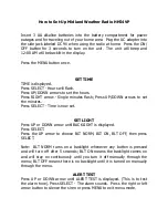
FEATURES
•
Wireless Weather Station (Figure 1).
•
Remote Temperature Sensor with optional
Channel 2 Probe (TX25U, Figure 2).
•
Indoor Temperature (˚F or ˚C) and Indoor Humidity.
•
Wireless Outdoor Temperature (˚F or ˚C).
•
Optional Channel 2 Temperature Probe.
•
Able to Receive up to 3 Remote Temperature
Sensors.
•
Wall Hanging or Free Standing.
ADDITIONAL EQUIPMENT (not included)
1. Two fresh AA 1.5V alkaline batteries for the wire-
less weather station.
2. Two fresh AAA 1.5V alkaline batteries for the re-
mote temperature sensor.
3. One, Philips screwdriver for mounting.
QUICK SETUP
Hint: Use good quality Alkaline Batteries; avoid re-
chargeable batteries.
1. Have the Wireless Weather Station and Tempera-
ture sensor 3 to 5 feet apart.
2. Batteries should be out of both units for 10 minutes.
3. Place the batteries into the Temperature sensor
first and next into the Wireless Weather Station.
4. DO NOT PRESS ANY BUTTONS FOR 15
MINUTES.
In this time the Wireless Weather Station and the tem-
perature sensor will begin to communicate with each
other, and the display will show both the indoor tem-
perature and an outdoor temperature. If the Wireless
12 or 24 Hour
Time Display
Connection w/
Sensor Icon
Low Battery
Indicator
Set / Channel
Button
Indoor Temperature
(˚F or ˚C)
Indoor Humidity
(%RH)
Channel Indicatop (1, 2
or 3)
Outdoor Temperature
(˚F or ˚C)
Minimum or Maximmum
Temperature &
Humidity
Minimum/Maximum/
+Button
Figure 1
Optional Probe
w/ 10 Foot Wire
Remote
Temperature
Sensor LCD
Temperature
Display
Wall-Mounting
Bracket
Figure 2
P.2
FCC ID: OMOTX25U (transmitter)
RF Exposure mobile:
The internal / external antennas used for this mobile transmitter must pro-
vide a separation distance of at least 20 cm (8 inches) from all persons and
must not be co-located or operating in conjunction with any other antenna
or transmitter.”
Statement according to FCC part 15.19:
This device complies with Part 15 of the FCC Rules. Operation is subject to
the following two conditions: (1) this device may not cause harmful
interference, and (2) this device must accept any interference received, in-
cluding interference that may cause undesired operation.
Statement according to FCC part 15.21:
Modifications not expressly approved by this company could void the user’s
authority to operate the equipment.
Statement according to FCC part 15.105:
NOTE: This equipment has been tested and found to comply with the limits
for a Class B digital device, pursuant to Part 15 of the FCC Rules. These
limits are designed to provide reasonable protection against harmful inter-
ference in a residential installation. This equipment generates, uses and
can radiate radio frequency energy and, if not installed and used in accor-
dance with the instructions, may cause harmful interference to radio
communications.
However, there is no guarantee that interference will not occur in a particu-
lar installation. If this equipment does cause harmful interference to radio or
television reception, which can be determined by turning the equipment off
and on, the user is encouraged to try to correct the interference by one or
more of the following measures:
• Reorient or relocate the receiving antenna.
• Increase the separation between the equipment and receiver.
• Connect the equipment into an outlet on a circuit different from that to
which the receiver is connected.
• Consult the dealer or an experienced radio/TV technician for help