La Crosse Technology WS-7095U, Instruction Manual
The La Crosse Technology WS-7095U is a reliable weather station that provides accurate weather information. Make sure to refer to the Instruction Manual for set up and operation. The manual can be downloaded for free from manualshive.com, giving you easy access to all the information you need.
Share
Download


Reviews:
No comments
Related manuals for WS-7095U
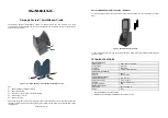
Skorpio
Brand: Datalogic Pages: 2

330-2315
Brand: La Crosse Technology Pages: 22

WS2300
Brand: La Crosse Technology Pages: 19

7525C
Brand: Psion Teklogix Pages: 52

TPW599C
Brand: YTORA Pages: 8

WS-7394U
Brand: La Crosse Technology Pages: 24

P-3036
Brand: Channel Vision Pages: 9

WH6000
Brand: Froggit Pages: 34

LOWSB510PB
Brand: Logia Pages: 38

LOWSC510WB
Brand: Logia Pages: 40

GSR90DABI
Brand: Goodmans Pages: 10

iP29
Brand: iHome Pages: 11

iH30
Brand: iHome Pages: 19

TASER Axon Dock
Brand: Axon Pages: 44

308-145B
Brand: La Crosse Pages: 2

WS-8025AL
Brand: La Crosse Technology Pages: 33

WS-8015U
Brand: La Crosse Technology Pages: 36

Tomorrow's Weather Today WS-7394U-IT
Brand: La Crosse Technology Pages: 23


