background image

Satellite T

elevision

KVH

TracV

ision

® 

4

technical

manual

Installation 

Configuration

Maintenance

A Guide to TracVision 4

Summary of Contents for TracVision 4

Page 1: ...Satellite Television KVH TracVision 4 technical manual Installation Configuration Maintenance A Guide to TracVision 4...

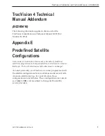
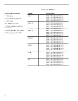
Page 2: ...or corrections have been made to the table of predefined satellite configurations for European satellites corrections are noted in bold type The North American satellite data remains unchanged As note...

Page 3: ...1 V H 3 11660 27500 34 0x0031 V L 3 12154 27500 34 0x0031 H H 3 11522 27500 34 0x0031 H L 3 Hotbird 12073 27500 34 0x013E V H 3 11958 27500 34 0x013E V L 3 11862 27500 34 0x013E H H 3 11862 27500 34 0...

Page 4: ...45 45 86 70 77 e mail info kvh com e mail info kvh dk Internet www kvh com Internet www kvh com A helpful tip that either directs you to a related area within the manual or offers suggestions on gett...

Page 5: ...ies Inc DIRECTV is an official trademark of DIRECTV Inc a unit of GM Hughes Electronics DISH Network is an official trademark of EchoStar Communications Corporation ExpressVu is a property of Bell Exp...

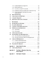
Page 6: ...Ground Cable 2 9 2 3 5 Installing the Switchplate 2 10 2 3 6 Connecting an Antenna RF Signal Cable to the IRD 2 10 2 3 6 1 Connecting the Antenna RF Signal Cables to a Multiswitch North American Syst...

Page 7: ...ventive Maintenance 4 1 4 3 TracVision 4 Field Replaceable Units 4 2 4 4 PCB Removal and Replacement 4 4 4 4 1 CPU Board 4 5 4 4 2 RF Detector 4 5 4 5 Antenna Gyro Assembly 4 7 4 6 Elevation Motor and...

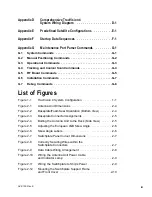
Page 8: ...igure 2 1 Antenna Unit Dimensions 2 4 Figure 2 2 Baseplate Foam Seal Orientation Bottom View 2 4 Figure 2 3 Baseplate Connector Assignments 2 5 Figure 2 4 Bolting the Antenna Unit to the Deck Side Vie...

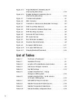
Page 9: ...gure 4 8 Elevation Drive Mechanism 4 9 Figure 4 9 European LNB Removal 4 11 Figure 4 10 U S style LNB Removal 4 11 Figure 4 11 Shipping Restraint Placement 4 12 List of Tables Table 1 1 TracVision 4 P...

Page 10: ...pecifications A 1 Table A 3 TracVision 4 Performance Specifications A 1 Table G 1 System Commands G 1 Table G 2 Manual Positioning Commands G 2 Table G 3 Operational Commands G 3 Table G 4 Tracking an...

Page 11: ......

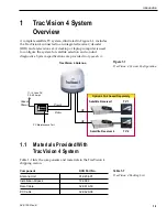
Page 12: ...A 1 1 Materials Provided With TracVision 4 System Table 1 1 lists the components and materials in the TracVision 4 shipping carton Component KVH Part No Antenna Unit 01 0234 01 Installation Kitpack 72...

Page 13: ...No Power Cable 32 0510 50 RF Cable 32 0417 50 IRD Ground Wire 32 0583 50 Switchplate 02 1023 TracVision 4 Technical Manual 54 0150 TracVision 4 User s Guide 54 0150 01 1 2 TracVision 4 Installation an...

Page 14: ...ohms cable for a second RF signal cable if necessary Crimp tool LRC L3011B or equivalent Light hammer center punch tape scriber pencil Terminal lug crimping tool wire strippers A PC with terminal emul...

Page 15: ...t of line with nearby radars as their energy levels may overload the antenna s front end circuits If necessary position the Antenna Unit so it is at least four feet 1 3 meters above or below the level...

Page 16: ...ts centerline reference MUST be parallel to it Be sure to account for the radome height and the base dimensions illustrated in Figure 2 1 Antenna Unit Mounting Procedure 1 Using the base dimensions pr...

Page 17: ...ttom Do not remove the paper backing at this time Align the seal with the vessel s fore and aft line and the small end pointed forward as shown in Figure 2 2 Scribe a line all around the seal 2 4 Trac...

Page 18: ...h at higher frequencies 8 Remove the foam shipping restraint from the Antenna Unit 9 Place the baseplate over the holes drilled in the foundation ensuring the forward arrow points toward the bow Rotat...

Page 19: ...ocation Adjusting the LNB Skew Angle 1 Turn off the power to the Antenna Unit 2 Remove the radome and set it aside 3 Loosen the two wing screws securing the LNB within the choke feed as illustrated in...

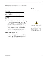
Page 20: ...he switchplate connectors and ship s power Tips for Safe and Successful Wiring When attaching cables to the TracVision 4 switchplate connectors make sure the insulation is stripped back approximately...

Page 21: ...tenna Unit Power Cable Find the TracVision 4 power cable where it comes through the panel cutout made earlier Wire the antenna unit power cable to the switchplate connectors as indicated in Figure 2 1...

Page 22: ...wire to any suitable screw on the rear panel of the IRD with a good contact with the IRD chassis The other end should be connected to a suitable ground ideally the Ground connector on the switchplate...

Page 23: ...ith F type connectors One end should be connected to the plug labeled RF1 on the base of the TracVision 4 system The other connector should be connected to the IRD plug labeled LNB or ANT SAT If a sec...

Page 24: ...with the manufacturer s instruction sheet 1 Connect the RF cable tagged RF1 to the multiswitch input labeled LNB RHCP 13V 2 Connect a second RF cable to the antenna unit s RF2 plug and to the multiswi...

Page 25: ...HF LHCP 18v Out 1 Out 2 Out 3 Out 4 DC Power IRD 1 IRD 2 IRD 4 IRD 3 RF Splitters Power Dividers Bow Figure 2 14 Multiple Multiswitch Installation North American Systems Only Starboard RF1 RF2 Port J1...

Page 26: ...d satellite settings as follows Antenna Alternative 1 Satellite A Antenna Alternative 2 Satellite B Section 2 5 Selecting the Active Satellite provides details on the satellite installation process Pr...

Page 27: ...e satellite pairs Two of these satellites may be selected to reside in the system s active memory as Satellites A and B 2 14 TracVision 4 Installation and Technical Manual DSS_101 DSS_119 Echo_61 Echo...

Page 28: ...edure requires terminal emulation software such as PROCOMM Windows Terminal or Windows 95 98 Hyperterminal Use the settings appropriate to your application 1 Connect one end of the PC data cable to th...

Page 29: ...s it should acquire and track This step should be carried out the first time a satellite is selected allowing the system to carry out the initial download of the channel guide To do so enter the Satel...

Page 30: ...ing the Active Satellite it is necessary to provide initial longitude data regarding the user defined satellite To do so enter the SATCONFIG parser command via PC as follows Command SATCONFIG USERX YY...

Page 31: ...e LNB down conversion frequency l low h high u USA D decoding type 0 test 1 DSS A 2 DSS B 3 DVB This information has to be entered for each of the four transponder categories vertical high vertical lo...

Page 32: ...n the SATLISTA list An Example of Configuring a User defined Satellite The following is an example of configuring the fictional YOURSAT 101 as the USER1 configured satellite Prior to configuring this...

Page 33: ...s 1 start bit 1 stop bit no flow control 3 Apply power to the TracVision 4 system and allow the system to complete full initialization Data should be scrolling on the PC display to identify any system...

Page 34: ...X X X X X X X X Snowy or pixelating television picture X X X X O u t s i d e s a t e l l i t e c o v e r a g e z o n e S e c t i o n 3 1 5 A n t e n n a g y r o f a u l t y S e c t i o n 3 3 L N B a...

Page 35: ...the power to the TracVision 4 unit the antenna gyro will record that variable motion as standing still This may cause the antenna to track improperly To solve this problem turn TracVision 4 off for a...

Page 36: ...the TracVision 4 unit is in the optimal location with regard to your radar unit 3 1 7 Incorrect or Loose RF Connectors As part of preventive maintenance described in Section 4 Maintenance KVH recomme...

Page 37: ...ssue with the use of any type of multiswitch 3 2 IRD Troubleshooting The IRD that was provided with your satellite television service may also be the cause of less than ideal operation First check the...

Page 38: ...5 pin connector adapter may be needed for some PCs 2 Open the terminal emulation software and establish the following settings 9600 baud no parity 8 data bits 1 start bit 1 stop bit no flow control 3...

Page 39: ......

Page 40: ...cannot be verified the warranty period will begin 30 days after the date of manufacture of the original product purchased For additional information on KVH warranty repair and liability policies plea...

Page 41: ...phone facsimile or e mail listings inside the front cover Replacement part numbers for field replaceable units FRUs that can be serviced in the field are listed in Table 4 1 These parts may be obtaine...

Page 42: ...by step procedures for removing and replacing those components that may be serviced Figure 4 1 depicts the location of a number of components within the TracVision 4 Antenna Unit 4 3 Maintenance 54 0...

Page 43: ...onnected by means of keyed Molex connectors Figure 4 3 shows the PCB arrangement connector locations and functions while Figure 4 4 on the next page shows how the printed circuit boards are mounted to...

Page 44: ...ng the Active Satellite 4 4 2 RF Detector The RF Detector receives operating voltages from both the CPU board and the IRD via the RF cable Ensure that all power including the IRD is turned off before...

Page 45: ...4 nut driver socket and set aside 7 Remove the RF Board and discard 8 Install the new RF Board making certain to align the Board so that the RF connectors are facing to the inside Figure 4 7 illustra...

Page 46: ...her P clip to the Antenna Reflector Set the nuts and washers aside 3 Disconnect the 7 pin Molex connector from the PCB Place the old Antenna Gyro assembly aside 4 Attach the 7 pin Molex to the new Ant...

Page 47: ...ALT cr while the system is performing the limit switch initialization routine The system will complete the initialization function by finding the azimuth and elevation switch limits and then go to the...

Page 48: ...y 4 6 1 Drive Belt Removal and Replacement 1 Loosen 2 8 32 x 5 8 screws until the motor is free to move upward Raise the motor to the top of the slots and retighten the screws to hold it there 2 Roll...

Page 49: ...g Loctite 425 or equivalent where each screw protrudes from the plate 4 Install the new motor with the open holes in the motor mounting plate behind the slots in the frame and the motor connector fac...

Page 50: ...it has the same skew value observed in Step 2 5 Apply a small amount of thread locking compound e g Loctite 425 or equivalent non permanent threadlocker to the screw threads and tighten the wing scre...

Page 51: ...position as shown in Figure 4 11 4 Place the foam shipping restraint label side up between the reflector and the azimuth motor as illustrated in Figure 4 11 The reflector should now be captured behind...

Page 52: ...amps peak Antenna System Performance Minimum EIRP 50 51 dB Elevation range 15 85 Azimuth range 720 Pitch roll range 15 Pitch roll rate 45 second Turn rate 45 second Yaw 90 in 10 seconds Tracking rate...

Page 53: ......

Page 54: ...Appendix B TracVision 4 Baseplate Mounting Holes Template A template for the four mounting holes is presented on the following page B 1 TracVision 4 Baseplate Mounting Holes Template 54 0150 Rev E...

Page 55: ...Vision 4 Baseplate Mounting Holes Template Drill 3 8 10 mm Bolt Hole 9 229 mm 3 80 mm Drill 3 8 10 mm Bolt Hole Drill 3 8 10 mm Bolt Hole Drill 3 8 10 mm Bolt Hole Cut out for Cable Access 9 229 mm 9...

Page 56: ......

Page 57: ...Appendix C Switchplate Template C 1 Switchplate Template 54 0150 Rev E 3 82 97 mm 32 8 mm 2 36 60 mm 16 4 mm 3 19 81 mm 2 05 52 mm Panel Cutout 3 32 3 mm dia...

Page 58: ......

Page 59: ...rehensive TracVision 4 wiring diagram is unavailable in PDF format If you require a copy of this wiring diagram please contact KVH Technical Support at 1 401 847 3327 or via email at techs kvh com A c...

Page 60: ......

Page 61: ...H L 3 Astra 2S 11972 27500 23 0x0020 V H 3 00000 27500 34 0x0000 V L 3 12226 27500 23 0x0020 H H 3 00000 27500 34 0x0000 H L 3 Hispasat 12152 27500 34 0x0031 V H 3 11660 27500 34 0x0031 V L 3 12154 27...

Page 62: ...06 H U 3 12383 20000 34 0X1006 H U 3 EchoStar 119 12374 20000 34 0X1004 V U 3 12374 20000 34 0X1004 V U 3 12381 20000 34 0X1004 H U 3 12381 20000 34 0X1004 H U 3 EchoStar 148 00000 20000 34 0X1004 V H...

Page 63: ...F F A 12238 20000 67 0X0000 H U 2 RF F A 12238 20000 67 0X0000 H U 2 RF F B 12374 20000 34 0X1004 V U 3 Satellite configuration data Satellite B RF F B 12374 20000 34 0X1004 V U 3 RF F B 12381 20000 3...

Page 64: ...5 417 RF S A H U V Satellite Found AZ 119 1 EL 33 4 RF 1767 Entering Tracking POS 149 8 33 4 812 RF S A H U V RF S A V U V RF Freeze DAC 00561 POS 130 4 32 5 2673 POS 129 7 31 9 2232 POS 129 1 31 4 22...

Page 65: ...responded to with an echo that is if you type ZAP for example and press ENTER the response will be the command you have entered For other commands the response is specific for each command such as VE...

Page 66: ...Angle Function commands a manual azimuth angle that the mechanism moves to Command AZ xxxx range is 0000 3599 Argument desired azimuth angle of the mechanism relative to external magnetic reference o...

Page 67: ...Function commands a 0 1 deg UP manual step in elevation angle Command 8 Argument none Response echoes the command Elevation DOWN Step Function commands a 0 1 deg DOWN manual step in elevation angle Co...

Page 68: ...onse Wrap Angle xxxx G 4 Tracking and Conical Scan Commands Target Location Function reports the target location in antenna frame Data format is E for elevation in degrees 000 900 and A for azimuth in...

Page 69: ...be set to invalid when the frequency is set to 00000 to indicate that there is not a frequency to track for the LNB tone and voltage setting Report RF Tracking Parameters Function reports all RF trac...

Page 70: ...the satellite transponder symbol rate in Mbit sec 01000 29999 C the FEC code e g 12 23 34 56 67 78 ID the satellite network ID in hexidecimal format 0x P the LNB polarization v vertical h horizontal B...

Page 71: ...s Function report names for all configured satellites Command SATLISTA Response SATLISTA sat_name1 sat_nameX Report Valid Satellite B Selections Function report names for all valid satellite B selecti...

Page 72: ...set Angles Function reports system offset angles Command OFFSETS OFFSETS XXXXX YYYY Response Offsets XXXXX X XXXXX X Where X new azimuth offset 1800 1800 Y new elevation angle 450 450 Apply Default Va...

Page 73: ...lite tracked or updates the last tracked satellite to the value input if it is different from the current value Command LASTSAT LASTSAT X Response Last sat_name Where X A updates to satellite A or X B...

Page 74: ......

Page 75: ...Department at 1 401 847 3327 or send an e mail to techs kvh com to obtain the RMA number Write the number in large clear characters on the outside of the box To avoid confusion and misunderstandings s...

Page 76: ...ax 401 849 0045 E Mail info kvh com Internet http www kvh com KVH Europe A S Ved Klaedebo 12 2970 Hoersholm Denmark Phone 45 45 160 180 Fax 45 45 867 077 E Mail info kvh dk Internet http www kvh com K...

Reviews: