Kutai electronics V-DOG2, User Manual
Introducing the Kutai Electronics V-DOG2 - a cutting-edge device perfect for power management solutions. To get the most out of this incredible product, make sure to download the free user manual available on our website. Unlock its full potential with our comprehensive manual and unleash the power of V-DOG2.
Share
Download


Reviews:
No comments
Related manuals for V-DOG2

96-007
Brand: Gadgets and Gear Pages: 2

Sentinel
Brand: Unipar Pages: 10

FD8166A-N
Brand: Vivotek Pages: 2

FD9371-EHTV
Brand: Vivotek Pages: 2

HSUI-H75DxZ2U8
Brand: Hitron Pages: 21

JA-162A-US
Brand: jablotron Pages: 2

Pro Alarm System AP5500
Brand: ELRO Pages: 8

EWS2
Brand: Eldes Pages: 8

Xpy Series
Brand: Nexxt Pages: 10

Axis 210
Brand: Axis Pages: 42

XND-6081F
Brand: Wisenet Pages: 65

HB-4040S
Brand: Saferhomee Pages: 14

S19-310JJ
Brand: Bradley Pages: 5
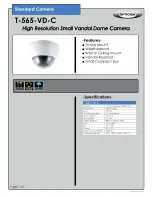
T-565-VD-C
Brand: OPTICOM Pages: 1

Home 502M
Brand: Viper Pages: 4

FE-12MPMIPS06-F01
Brand: I-View Pages: 8

B1MS02-ZW-AU
Brand: B.one Pages: 9

SDT200
Brand: SDT Pages: 19


