KT&C KNC-p3LR4IR, Quick Operation Manual
The KT&C KNC-p3LR4IR Quick Operation Manual is a comprehensive user guide designed to assist customers in using their surveillance camera effectively. Easily accessible for free download on our website, this manual ensures that users can maximize the product's potential.
Share
Download


Reviews:
No comments
Related manuals for KNC-p3LR4IR

SND-7080
Brand: SAA Asia Limited Pages: 76

SR230
Brand: Paradox Pages: 2

SP5500
Brand: Paradox Pages: 2

Digiplex EVO DGP2-640
Brand: Paradox Pages: 24

QS1230-840
Brand: QOLSYS Pages: 3

VISTA-32FB
Brand: ADEMCO Pages: 56

JA-152P
Brand: jablotron Pages: 2

E100 Wirefree
Brand: Response Alarms Pages: 16

ECI-B14F2
Brand: HIKVISION Pages: 21

Predix-100/24
Brand: Umirs Europe Pages: 24

BX811
Brand: Tracker Pages: 18

SNC-431RDIA
Brand: Santec Pages: 8

BLOCKSTOP BS IKA 1.8
Brand: Bornack Pages: 16

IPCB72501
Brand: Abus Pages: 18

BU-19
Brand: Lawmate Pages: 1

HTP-T13MG28D
Brand: Huntcctv Pages: 33

GOVIDEO SMC6
Brand: SALIX Pages: 12
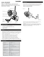
SM-703DT
Brand: SecurityMan Pages: 2


